Pressurized drainage tube for chest

A drainage tube and thoracic cavity technology, applied in the field of thoracic cavity drainage after surgery, can solve the problems of patients’ pain, pleural cavity infection, and increased amount of bleeding and exudate, and achieve the effects of avoiding bleeding from the chest wall, balancing pressure, and solving gas accumulation

Inactive Publication Date: 2013-04-03
THE FIRST AFFILIATED HOSPITAL OF SOOCHOW UNIV
View PDF4 Cites 1 Cited by
  • Summary
  • Abstract
  • Description
  • Claims
  • Application Information

AI Technical Summary

Problems solved by technology

[0002] After thoracotomy, due to lobectomy or pneumonectomy, there is a huge cavity left in the thoracic cavity, and the negative pressure in the thoracic cavity generated by postoperative breathing may increase the amount of blood and fluid in the thoracic cavity. Second or even multiple thoracotomy to stop bleeding will increase the patient's medical expenses and prolong the hospital stay
[0003] The traditional way to deal with extensive bleeding in the chest cavity is gauze filling: by using medical uterine gauze, the residual cavity in the chest cavity is filled in a certain order, and the gauze is gradually drawn out 2-3 days after the operation. The problem is that the opening of the thorax after surgery is likely to cause intrathoracic infection, and at the same time, the process of pulling out the gauze from the chest will cause great pain to the patient, and if the pleural cavity rebleeds after the gauze is pulled out, it will not be able to be repacked and can only be performed again. Chest hemostasis

Method used


Image

  • Pressurized drainage tube for chest
  • Pressurized drainage tube for chest
  • Pressurized drainage tube for chest

Examples


Embodiment 1

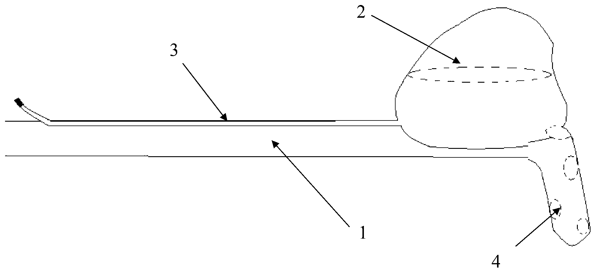
[0025] See figure 1 , figure 1 It is a structural schematic diagram of a pressurized drainage tube for upper lobectomy disclosed by the present invention. As shown in the figure, a pressurized drainage tube for chest cavity is proposed according to the purpose of the present invention. It includes a chest tube 1, an air bag 2 arranged on the chest tube 1, an air intake tube 3 for inflating the air bag 2 is arranged on one side of the chest tube 1, and at least one drainage hole 4 is opened on the front end of the air bag 2 on the chest tube 1 The shape of the airbag 2 after inflation matches the shape of the upper lung lobe in the chest cavity, and the airbag 2 can fill the chest cavity to balance the pressure of the chest cavity after inflation. By designing the inflated shape of the airbag to the shape of the upper lung lobe, it is suitable for hemostasis in patients with upper lobectomy to balance the pressure in the thoracic cavity.

[0026] The air bag 2 is set on the s...

Embodiment 2

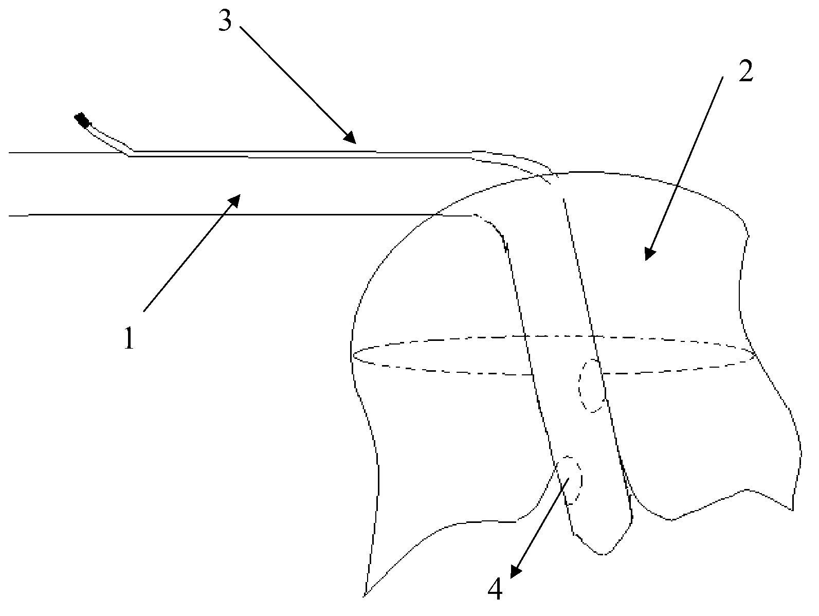
[0036] Such as figure 2 As shown, the rest are the same as in Example 1, the difference is that the airbag is arranged on the lower side of the chest tube, and the shape of the airbag 2 after inflating matches the shape of the lower lobe or middle and lower lobe of the chest cavity, and the airbag 2 can be filled after inflating Thoracic cavity to equalize the pressure in the chest cavity. By designing the inflated shape of the airbag to the shape of the lower lobe or the middle and lower lobe, it is suitable for hemostasis in patients with lower or middle and lower lobectomy to balance the pressure in the thoracic cavity.

Embodiment 3

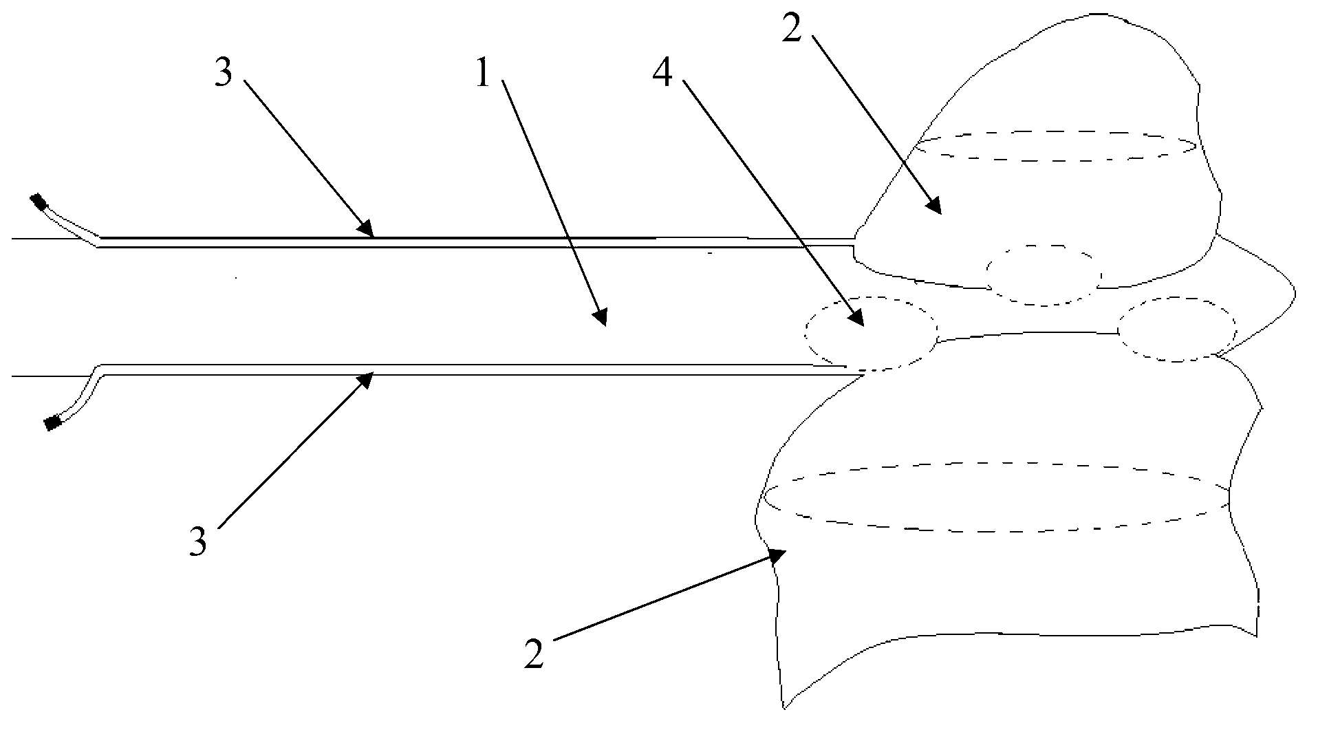
[0038] Such as image 3 As shown, the rest are the same as in Example 1, the difference is that the airbags are two located on both sides of the chest tube 1, the airbags on both sides are spliced ​​to form the entire lung, which matches the shape of the whole lung, and the airbag 2 can be filled after inflated Thoracic cavity to equalize the pressure in the chest cavity. The shape of the whole lung is formed by splicing the inflated airbags, which is suitable for hemostasis in patients with pneumonectomy to balance the pressure in the thoracic cavity.

[0039] In addition to being used for thoracopulmonary resection and filling, the present invention can also be used for other abdominal organs such as spleen removal, etc., as long as the upper and lower airbag shapes are designed to correspond to organ shapes, and the corresponding organ shapes can be formed by splicing after inflating , there is no specific limit.

[0040]The invention discloses a pressurized drainage tube...


PUM


Abstract

The invention discloses a pressurized drainage tube for a chest. Air bags are arranged on a chest tube; the air bags are aerated to be expanded continuously, a shape of the aerated air bags is matched with the shape of lung lobes, or matched with the shape of other spleens; when an organ is removed, the chest tube is inserted into the chest and then the air bags on the chest tube are aerated, so that the air bags effectively fill the chest to ensure equalization of the pressure in a human body, reduce even avoid the phenomenon of exudation of a chest wall; the pressure in the air bags can be increased or reduced according to the situation of exudation in the chest after operation, the pressure in the air bags is gradually reduced along with post operation time, then residual lung is expanded correspondingly, and finally the aim of removing the pressurized drainage tube is achieved; and meanwhile, the air bags companion the chest tube, once the air bags leak or air and blood exist in a cavity, the air and the blood can be drained by drainage holes in the chest tube through the chest tube timely, and the problems of discharge of pneumatosis and dropsy in the chest are also effectively solved.

Description

technical field [0001] The invention relates to the technical field of postoperative thoracic cavity drainage, in particular to a pressurized drainage tube for the thoracic cavity. Background technique [0002] After thoracotomy, due to lobectomy or pneumonectomy, there is a huge cavity left in the thoracic cavity, and the negative pressure in the thoracic cavity generated by postoperative breathing may increase the amount of blood and fluid in the thoracic cavity. Second or even multiple thoracotomy to stop bleeding will increase the patient's medical expenses and prolong the hospital stay. [0003] The traditional way to deal with extensive bleeding in the chest cavity is gauze filling: by using medical uterine gauze, the residual cavity in the chest cavity is filled in a certain order, and the gauze is gradually drawn out 2-3 days after the operation. The problem is that the opening of the thorax after surgery is likely to cause intrathoracic infection, and at the same t...

Claims


Application Information

Patent Timeline
IPC IPC(8): A61M25/10A61M27/00A61B17/12
Inventor 倪斌
Owner THE FIRST AFFILIATED HOSPITAL OF SOOCHOW UNIV
Why Eureka
Try Eureka