Dual display structure

A dual-screen, screen technology, used in lighting and heating equipment, instruments, electrical digital data processing, etc., can solve problems such as unmaintainability, unsightly, and user inconvenience

Inactive Publication Date: 2013-06-26
ASUSTEK COMPUTER INC
View PDF4 Cites 9 Cited by
  • Summary
  • Abstract
  • Description
  • Claims
  • Application Information

AI Technical Summary

Benefits of technology

The double screen mechanism helps cram down its size while still providing an effective display for both screens. It allows two different modules (the main part) sharing their own light guides/reflectors instead of being placed next to each other's surface. This design also includes support structures that help it work properly without getting stuck due to gravity issues. Overall, this technology makes displaying multiple applications easier than traditional displays like liquid crystal panels.

Problems solved by technology

This patented technical problem addressed in this patents relates to how thin or bulky mobile phones like Tablets (tablets) should keep their display faces upward without getting overloaded by adding extra components that increase its overall height.

Method used


Image

  • Dual display structure
  • Dual display structure
  • Dual display structure

Examples


Embodiment Construction

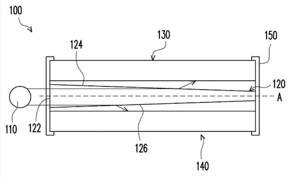
[0018] figure 1 is a schematic diagram of a dual-screen structure according to the first embodiment of the present invention. see figure 1 , the double screen structure 100 of this embodiment includes a light source 110 , a light guide plate 120 , a first screen module 130 and a second screen module 140 .

[0019] In this embodiment, the light source 110 is a light emitting diode, but the type of the light source 110 is not limited thereto. The light guide plate 120 includes a light incident surface 122 , a first light exit surface 124 and a second light exit surface 126 . The first screen module 130 and the second screen module 140 are arranged parallel to and opposite to each other on one side of the first light-emitting surface 124 and the second light-emitting surface 126 .

[0020] The light emitted by the light source 110 enters the light guide plate 120 from the light incident surface 122 , and then irradiates to the first screen module 130 and the second screen module


PUM


Abstract

A dual display structure including a light source, a light guide plate, a first display module and a second display module is provided. The light guide plate includes a light incident surface, a first light exiting surface and a second light exiting surface. The first and second display modules are respectively disposed at one side of the first and second exiting surfaces in parallel and back to each other. Light emitted from the light source enters the light guide plate through the light incident surface and emits to the first display module and the second display module through the first light exiting surface and the second light exiting surface.

Description


Claims


Application Information

Patent Timeline
Owner ASUSTEK COMPUTER INC
Why Eureka
Try Eureka