Infrared perspective imaging detecting chip

An imaging and infrared technology, applied in the direction of electric radiation detectors, etc., can solve the problems of large volume and power consumption of imaging devices, poor adaptability to targets and environments, difficulty in covering target beams, etc., and achieve wide measurement spectrum, convenient plugging, The effect of high structural stability

Active Publication Date: 2014-01-15
HUAZHONG UNIV OF SCI & TECH
View PDF6 Cites 1 Cited by
  • Summary
  • Abstract
  • Description
  • Claims
  • Application Information

AI Technical Summary

Problems solved by technology

There are defects such as large volume and power consumption of the imaging device, high cost, low imaging efficiency, poor adaptability to the target and the environment, etc.
[0004] As far a

Method used


Image

  • Infrared perspective imaging detecting chip
  • Infrared perspective imaging detecting chip

Examples


Embodiment Construction

[0021] In order to make the objectives, technical solutions and advantages of the present invention clearer, the present invention will be further described in detail below with reference to the accompanying drawings and embodiments. It should be understood that the specific embodiments described herein are only used to explain the present invention, but not to limit the present invention. In addition, the technical features involved in the various embodiments of the present invention described below can be combined with each other as long as they do not conflict with each other.

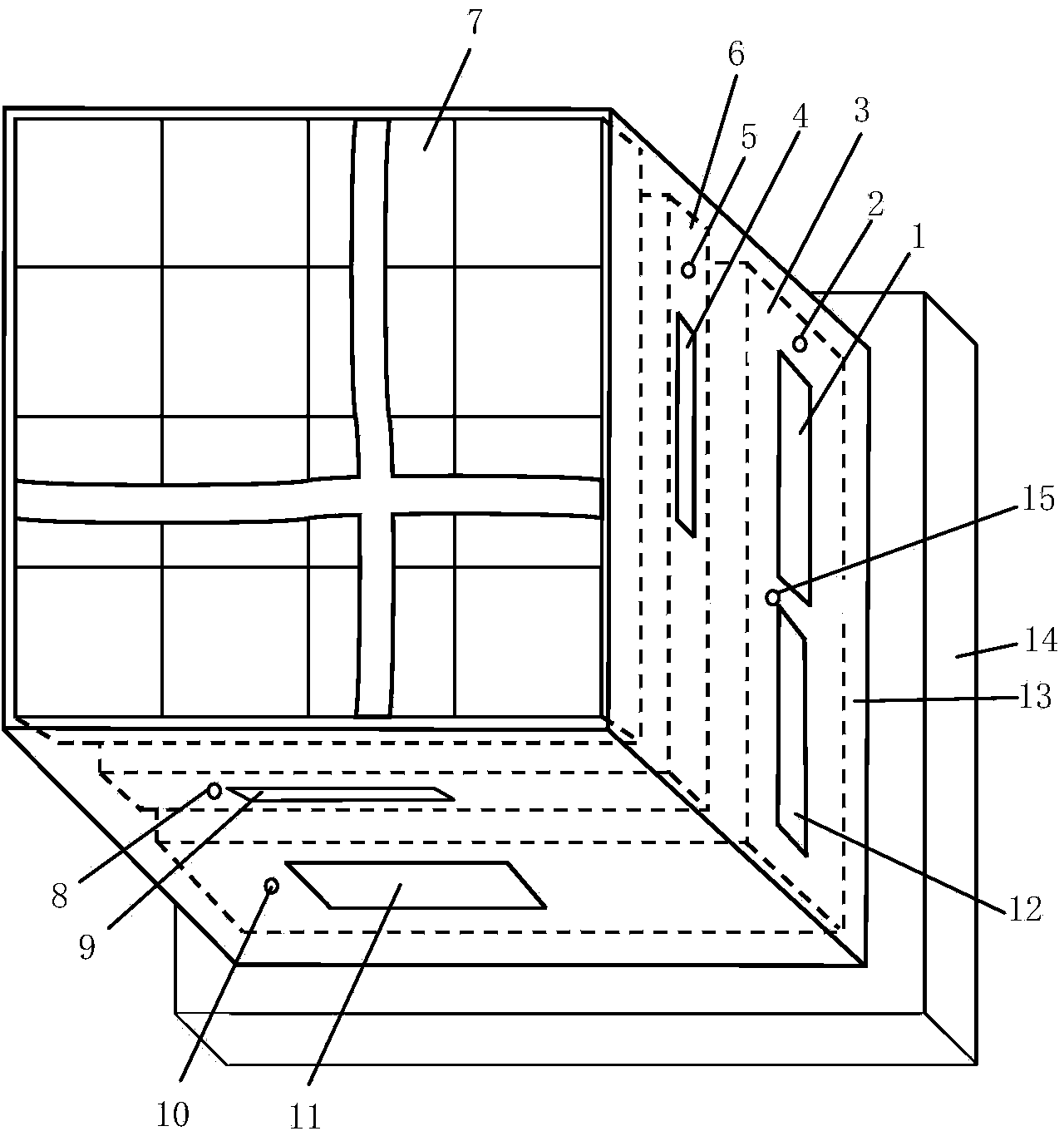
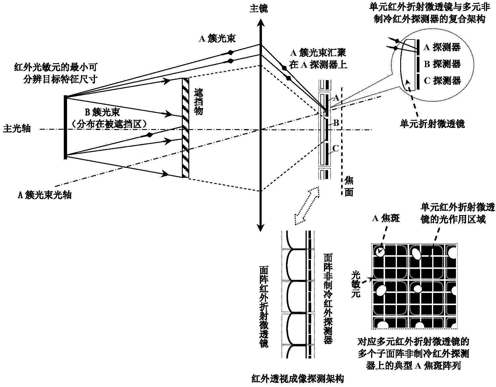
[0022] like figure 1 As shown, the infrared perspective imaging detection chip of the present invention includes: a ceramic shell 13, a metal support and a heat sink 14, a drive control and perspective image preprocessing module 3, an area array uncooled infrared detector 6, and an area array infrared refraction microlens 7.

[0023] The drive control and perspective image preprocessing module 3 , th


PUM


Abstract

The invention discloses an infrared perspective imaging detecting chip which a ceramic shell, a metal support, a heat dissipation board, a drive control and perspective image preprocessing module, an area array non-refrigeration infrared detector and an area array infrared refraction micro lens. The drive control and perspective image preprocessing module, the area array non-refrigeration infrared detector and the area array infrared refraction micro lens are coaxially and sequentially arranged in the ceramic shell. The rear portion of the ceramic shell is arranged on the top of the metal support and the top of the heat dissipation board. The drive control and perspective image preprocessing module is arranged at the joint of the rear portion of the ceramic shell, the metal support and the heat dissipation board. The area array non-refrigeration infrared detector is arranged on the top of the drive control and perspective image preprocessing module, and the area array infrared refraction micro lens is arranged on the top of the area array non-refrigeration infrared detector. The infrared perspective imaging detecting chip is compact in structure and has the advantages that single-chip perspective imaging detection is performed on an infrared target based on an infrared beam direction, the measuring precision is high, the infrared perspective imaging detecting chip is easily compatible or coupled with a conventional infrared optical system, and the adaptability of the target and the environment is good.

Description


Claims


Application Information

Patent Timeline
Owner HUAZHONG UNIV OF SCI & TECH
Why Eureka
Try Eureka