Sensor and method for providing high transfer rate in page-based optical data storage

Active Publication Date: 2008-11-04
ORACLE INT CORP
View PDF6 Cites 15 Cited by
  • Summary
  • Abstract
  • Description
  • Claims
  • Application Information

AI Technical Summary

Benefits of technology

[0010]The present invention generally contemplates encapsulating the active area of each pixel of a sensor array (i.e., detector) within a resonant cavity formed by two reflective surfaces. Encapsulation of the active area of each pixel generally increases the absorption due to the multiple passes and resulting enhancement of the optical field through the active layer. Accordingly, increased detector sensitivity may be achieved. Additionally, incorporation of a resonant cavity makes it possible to employ thinner active layer for each pixel without reducing the sensitivity of the sensor array. Furthermore one or more embodiments of the present invention may provide a mechanism for controlling and varying the resonant properties of the cavity, for effectively forming a tunable frequency selective resonant cavity enhanced sensor. Furthermore, one or more embodiments of the present invention may provide, inter alia, for separation of wavelength multiplexed images in holographic storage.

Problems solved by technology

However, these sensors have invariably been optimized for the high dynamic range and relatively low transfer rates required by consumer imaging and machine vision applications, not for data storage.
While such techniques have yielded substantial improvements in the frame transfer rates, they do not improve the optical properties of the sensor and sometimes contribute to their degradation.
For example, the integration of a greater number of electronic circuitry tends to reduce the photoactive area in each pixel, otherwise termed its fill factor, and thus contributes to reducing optical detection efficiency.

Method used


Image

  • Sensor and method for providing high transfer rate in page-based optical data storage
  • Sensor and method for providing high transfer rate in page-based optical data storage
  • Sensor and method for providing high transfer rate in page-based optical data storage

Examples


Embodiment Construction

[0019]One or more embodiments of the present invention are now described with reference to the Figures, where like reference numbers indicate like elements.

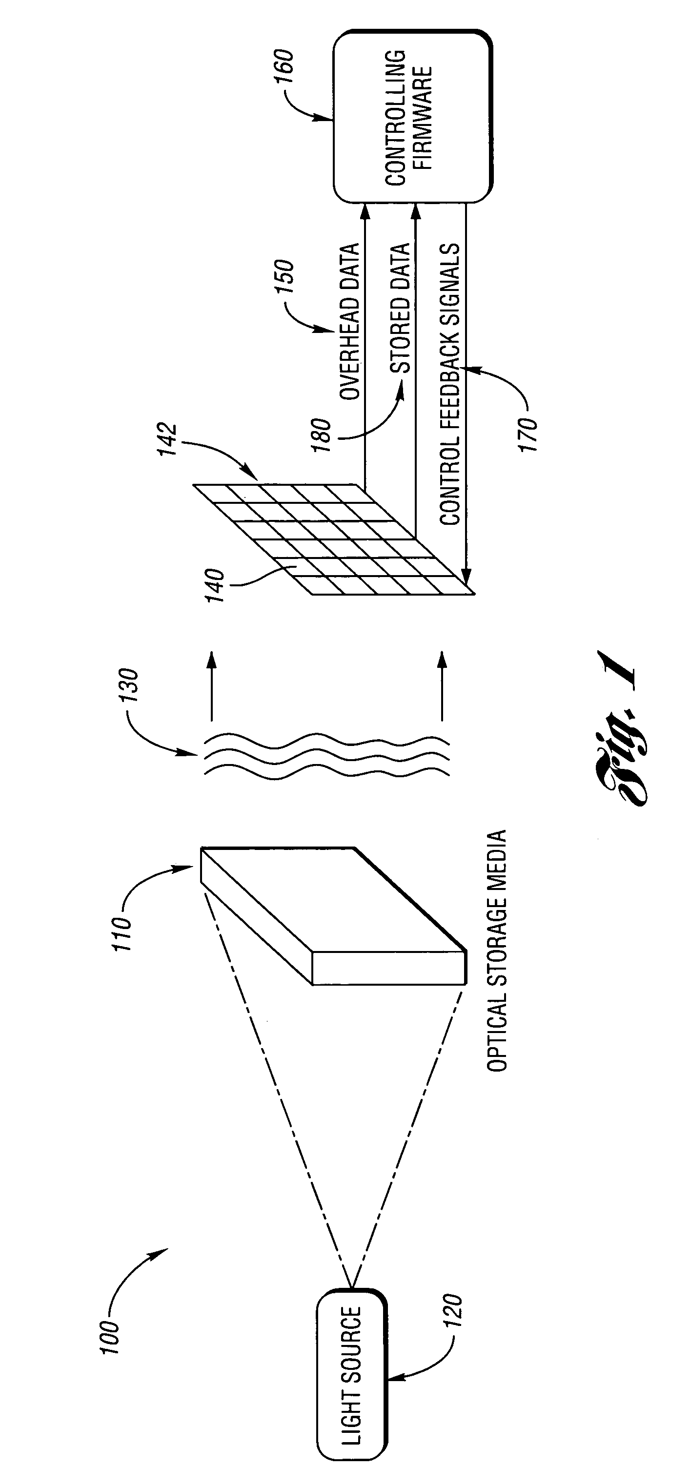
[0020]FIG. 1 is a high-level schematic diagram of a readout operation for a page-based optical data storage system 100 (e.g., implemented holographically, diffractively, etc.) according to one or more embodiments of the present invention. Optical medium 110 is generally illuminated by light source 120, providing a plane 130 of modulated signals representing the stored data. The modulated signals are detected by the photodetector array (i.e., sensor array) 142. The photodetector array 142 generally further comprises a plurality of pixels (i.e., sensors) 140.

[0021]From the photodetector array 142, data 180 is transferred out to the controlling firmware 160 and / or other logical apparatus. Depending on the level of integration of additional functionality on the photodetector array, other electronic signals 150, potentially representi...


PUM


Abstract

A sensor and method for page-based optical data storage. The sensor includes a partially-reflective mirror, a reflective mirror disposed substantially collinear with and spaced apart from the partially-reflective mirror, and an active layer disposed substantially collinear with and between the partially-reflective mirror and the reflective mirror. The partially-reflective mirror has a first and second side and transmits a portion of light incident on the first side. The reflective mirror reflects light incident on the reflective mirror toward the partially-reflective mirror. The active layer absorbs at least a portion of the light oscillating at the resonant frequency.

Description

BACKGROUND OF THE INVENTION[0001]1. Field of the Invention[0002]The present invention relates to page-based optical data storage and, in particular, to a sensor and method for providing increased transfer rates in page-based optical data storage.[0003]2. Background Art[0004]Traditional optical data storage technologies (e.g., CD and DVD) lag behind traditional magnetic data storage technologies (e.g., hard drives and tape) in transfer rates. Page-based optical data storage and retrieval offers the advantage of parallel optical data processing and may generally enable higher data transfer rates.[0005]In page-based optical data storage, a page of data is read by imaging a two-dimensional data page onto a two-dimensional detector. The detector detects the image, and the image is subsequently processed to decode the data contained therein. In general, the detector comprises an active (i.e., absorbing) layer for detecting the image of the two-dimensional data page.[0006]Page-based optica...

Claims


Application Information

Patent Timeline
IPC IPC(8): H01L31/00
CPCG11B7/0065G11B7/13H01L27/14621H01L27/14647H01L31/02165G11B2007/0009
Inventor SIGEL, CHRISTOPHE N.LEONHARDT, MICHAEL L.
Owner ORACLE INT CORP
Why Eureka
Try Eureka