Self-balancing type lathe fixture

A lathe fixture, self-balancing technology, applied in the direction of clamping, manufacturing tools, supports, etc., can solve the problem of simple and practical methods for lathe fixtures, achieve process man-hour balance, improve machining accuracy and surface quality, reduce Vibration and noise effects

Active Publication Date: 2015-04-01
JIANGXI JUST NUMERICAL CONTROL TECH
View PDF6 Cites 1 Cited by
  • Summary
  • Abstract
  • Description
  • Claims
  • Application Information

AI Technical Summary

Problems solved by technology

At present, the commonly used solution for one installation is to balance the counterweight. The

Method used


Image

  • Self-balancing type lathe fixture
  • Self-balancing type lathe fixture
  • Self-balancing type lathe fixture

Examples


Embodiment

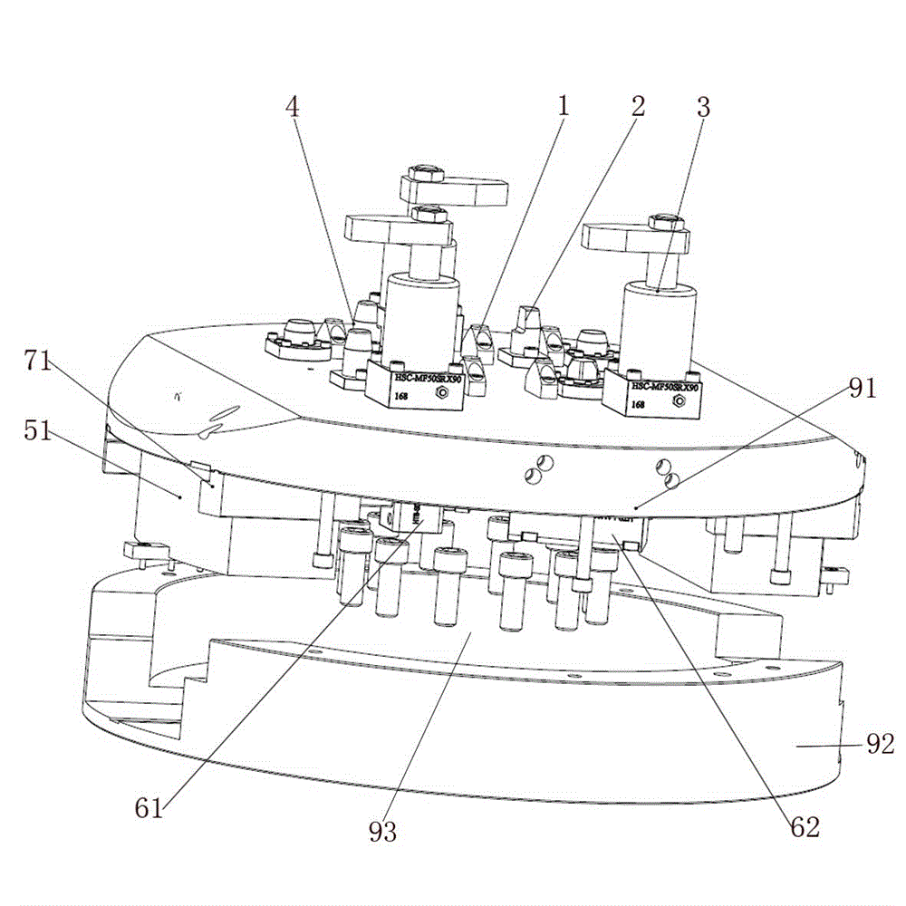
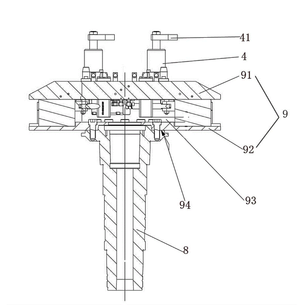
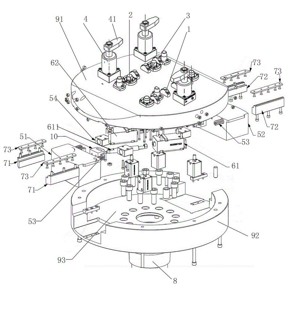
[0022] Example: see figure 1 —— image 3 .

[0023] The invention discloses a self-balancing lathe fixture, which includes a fixture table 9 connected with a machine tool spindle 8, a clamping piece is arranged on the top of the clamping piece 9, and the clamping piece includes a vertically arranged support Nail 1, fine positioning pin 2, pre-positioning pin 3 and corner hydraulic cylinder 4, the piston rod upper end of described corner hydraulic cylinder 4 is provided with horizontal pressure bar 41. The workpiece to be clamped is placed above the support nails 1 of the fixture table 9, and the three support nails 1 scattered above the fixture table 9 limit the three degrees of freedom of the workpiece. Two pre-positioning pins 3 realize the pre-positioning of the workpiece, and two precise positioning Pin 2 (one is a diamond pin) restricts three degrees of freedom of the workpiece, and the clamping of the workpiece is realized by driving the pressure rod 41 to move vertically


PUM


Abstract

The invention relates to a fixture for flow line production and especially relates to a self-balancing type lathe fixture. The self-balancing type lathe fixture comprises a fixture platform which is connected with a lathe spindle, wherein a clamping piece is arranged above the fixture platform; the fixture platform comprises an upper cover plate and a lower cover plate; the upper cover plate and the lower cover plate are oppositely arranged, are buckled together and forme a hollow equipment cavity; a balancing block is arranged in the equipment cavity; the balancing block horizontally moves under the driving of an external force; a guiding block and a limiting block are also arranged. Compared with a lathe fixture which is mounted twice, the vertical turning fixture can automatically realize balancing and can more effectively realize the process and labor-hour balancing of an automatic processing line.

Description


Claims


Application Information

Patent Timeline
Owner JIANGXI JUST NUMERICAL CONTROL TECH
Why Eureka
Try Eureka