Plug electrical connector

A technology of electrical connectors and plugs, which is applied in the direction of connection and connection device components, circuits, etc., can solve problems such as interference, electromagnetic interference, and poor shielding performance, to increase strength, increase aesthetics, and improve poor shielding design Effect

Active Publication Date: 2015-10-28
连展科技电子(昆山)有限公司
View PDF5 Cites 2 Cited by
  • Summary
  • Abstract
  • Description
  • Claims
  • Application Information

AI Technical Summary

Benefits of technology

This patented technology uses an improved way for create a shaped case with a smooth surface that increases its effectiveness against external influences such as water or dust. It does this without any openings at all, which makes them more durable over time compared to traditional methods like welded metal plates used previously. Additionally, these techniques help maintain good quality signals transmitted between electronic devices while reducing EMI emissions.

Problems solved by technology

This patented technical issue addressed in this patents relates to improving the quality of signal transfer between electronic devices caused by exposures from external sources such as EMI or radio frequency interruptions during data communication over USB interfaces like USB 2.0/3.

Method used


Image

  • Plug electrical connector
  • Plug electrical connector
  • Plug electrical connector

Examples


Embodiment Construction

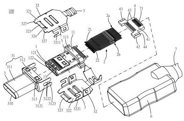
[0057] figure 1 It is an exploded schematic view of the electrical plug connector of the present invention. Please refer to figure 1 , is an embodiment of the electrical plug connector 100 of the present invention. In this embodiment, the electrical plug connector 100 is a micro USB (Type-C) connection interface specification. The electrical plug connector 100 includes an insulating body 1 , terminals 2 and a shielding shell 3 .

[0058] Figure 9 It is a schematic cross-sectional view of the casing after the combination of the previous casings of the present invention. Please refer to figure 1 again Figure 9 , here, the insulating body 1 includes a base 11, an upper plate 121, a lower plate 122 and a slot 13, the upper plate 121 and the lower plate 122 are arranged on one side of the base 11, and the slot 13 is defined on the upper Between the plate body 121 and the lower plate body 122 . Here, the insulating main body 1 is formed with a base 11 , an upper plate 121 , a


PUM


Abstract

A plug electrical connector comprises an insulated main body, terminals and a shielding housing. The insulated main body comprises a pedestal, plate bodies and a slot. The pedestal is provided with a groove, the plate bodies extend and are formed at one side of the pedestal, and the slot is arranged between the plate bodies. The terminals are arranged on the insulated main body, and each terminal is provided with a spring piece contact end which is arranged in the slot. The shielding housing covers the insulated main body, and the shielding housing comprises a rear cover and a front cover. The pedestal is arranged in the rear cover, the rear cover comprises an abutting plate which abuts against the groove, the front cover is drawn from the rear cover and is formed at the front side of the rear cover, the front cover protrudes from the front side of the rear cover, and the plate bodies are arranged in the front cover.

Description


Claims


Application Information

Patent Timeline
Owner 连展科技电子(昆山)有限公司
Why Eureka
Try Eureka