Lifting equipment

A technology of equipment and floor base, which is applied in the direction of lifting devices, lifting frames, etc., can solve problems such as difficult lifting methods, and achieve the effect of convenient processing

Inactive Publication Date: 2016-02-03
WUHU HENGHAO MACHINERY MFG
View PDF6 Cites 17 Cited by
  • Summary
  • Abstract
  • Description
  • Claims
  • Application Information

AI Technical Summary

Benefits of technology

This technology allows for easy handling by lifting or moving part(s) from one state into another without having them collide with each other during this process.

Problems solved by technology

The technical problem addressed by this patented technology relates how to efficiently move large items such as parts between different locations within an assembly process without causing them to fall over due to their weight being supported only on one side while they are moving around at some distance along its path through various stages of manufacturing processes.

Method used


Image

  • Lifting equipment
  • Lifting equipment

Examples


Embodiment Construction

[0012] In order to make the technical means, creative features, goals and effects achieved by the present invention easy to understand, the present invention will be further elaborated below.

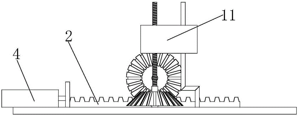
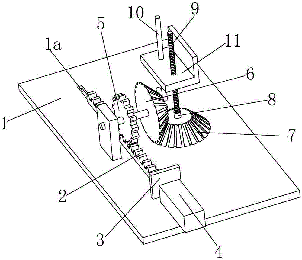
[0013] like figure 1 and figure 2 As shown, a lifting device mainly includes a base plate base 1, a chute 1a is opened on the base plate base 1 along the horizontal direction, a rack 2 is slidably installed on the chute 1a, and the left end of the rack 2 is connected with a The connecting plate 3 is connected with the cylinder 4 at the left end of the connecting plate 3 . The cylinder 4 can effectively drive the rack 2 to slide stably and horizontally.

[0014] The upper part of the rack 2 is meshed with a gear 5, the front end of the gear 5 is coaxially connected with a No. 1 bevel gear 6, and the No. 1 bevel gear 6 is meshed with a No. 2 bevel gear 7. The lower seat body 8 installed on the base plate seat 1, the upper end of the lower seat body 8 is equipped with a ball screw 9, the


PUM


Abstract

The invention relates to lifting equipment. The lifting equipment mainly comprises a bottom plate base. A sliding groove is formed in the bottom plate base in the horizontal direction. A rack is installed in the sliding groove in a sliding mode. A connecting plate is connected to the left end of the rack. An air cylinder is connected to the left end of the connecting plate. A gear is engaged with the upper portion of the rack. A first bevel gear is coaxially connected to the front end of the gear. The first bevel gear is engaged with a second bevel gear. The second bevel gear is connected with a lower base body installed on the bottom plate base in a rotating mode. A ball screw is installed at the upper end of the lower base body. A vertically-arranged unthreaded rod is arranged on the right side of the ball screw. A carrying plate which is in threaded connection with the ball screw is connected with the unthreaded rod in a sliding mode. The lifting equipment has the characteristics that a processed part can be vertically lifted and transported through a high-automatic tooth meshing mode, and therefore the indirect beneficial effects of convenient processing is achieved.

Description


Claims


Application Information

Patent Timeline
Owner WUHU HENGHAO MACHINERY MFG
Why Eureka
Try Eureka