Wind power blade tip lengthening method

A technology for wind power blades and extension sections, applied in the field of wind power blade tip extension, can solve the problems of increased construction cost and time, damage, and complicated construction, so as to reduce construction time and cost, improve controllability, and reduce construction complexity sexual effect

Inactive Publication Date: 2016-04-20
INST OF ENGINEERING THERMOPHYSICS - CHINESE ACAD OF SCI
View PDF4 Cites 20 Cited by
  • Summary
  • Abstract
  • Description
  • Claims
  • Application Information

AI Technical Summary

Benefits of technology

This technology allows for better control during the manufacturing process by extending the blaades without damaging them or distributing adhesive uniformly throughout it instead of just spread out across its surface. Additionally, this design increases the overall stability of the bladed structure while reducing their risk of damage due to external forces such as impacts. Overall, these improvements improve durability and performance efficiency when used in building materials like concrete slabs.

Problems solved by technology

Technological Problem addressed in this patented technical problem involves improving the performance and durability of wind driven generators due to increased airflow over longer lengths of rotor blinds used during normal operations compared to traditional designs where only one end of each blade remains fixedly attached to its own structure. Existing techniques involve adding extra material like steel plating onto these long ends but they may compromise safety measures and require complex connections between the extended portion connected to the main part of the generator's body.

Method used


Image

  • Wind power blade tip lengthening method
  • Wind power blade tip lengthening method
  • Wind power blade tip lengthening method

Examples


Embodiment Construction

[0026] In order to make the purpose and technical solution of the present invention clearer, the present invention will be further described in detail below in conjunction with specific embodiments and with reference to the accompanying drawings.

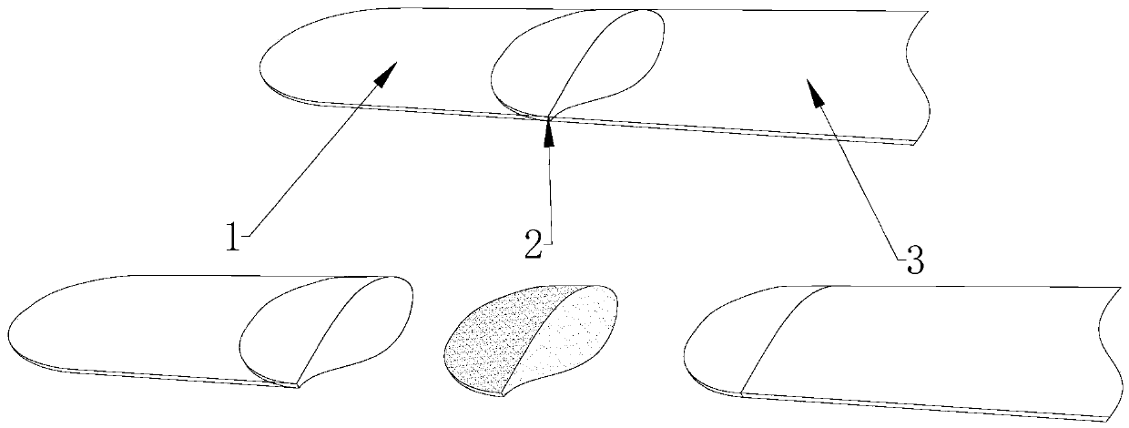
[0027] Such as figure 1 As shown, the blade tip extension method of the present invention is to bond the blade tip extension section 1 to the base blade 3 through the structural glue 2, so as to increase the blade length and achieve the purpose of increasing the power generation. It is characterized in that the method includes Make the blade tip extension, make and install auxiliary tooling, build the glue injection system, glue injection and post-processing four steps.

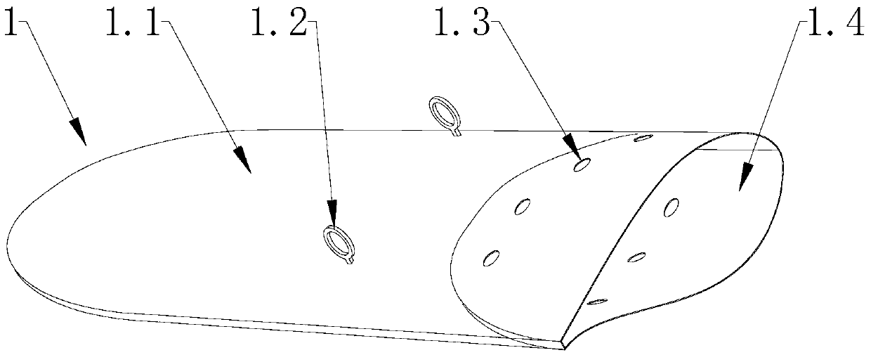
[0028] 1. Make the blade tip extension

[0029] Tip extension 1 as figure 2 As shown, including extension section connection end 1.4, extension section main body 1.1, suspension ring 1.2 and glue injection hole 1.3, the inner contour of extension section connection


PUM


Abstract

The invention discloses a wind power blade tip lengthening method. By bonding a blade tip lengthening section with a basic blade through a structural adhesive to increase the length of the blade, the purpose of improving the generating capacity is achieved. On the premise that the appearance of the basic blade is not destroyed, the structural adhesive can be uniformly and fully applied to an bonding area of the blade tip lengthening section and the original blade by constructing an adhesive injecting system, therefore, the bonding strength is effectively improved, the construction complexity is reduced, the construction time is shortened, and the construction cost is lowered.

Description


Claims


Application Information

Patent Timeline
Owner INST OF ENGINEERING THERMOPHYSICS - CHINESE ACAD OF SCI
Why Eureka
Try Eureka