Axial piston machine

An axial piston engine and piston technology, which is used in reciprocating piston engines, mechanical equipment, variable capacity engines, etc., can solve the problems of unfavorable deformation and wear at the bottom of the bearing, and achieve the effect of simple manufacturing.

Inactive Publication Date: 2016-06-15
ROBERT BOSCH GMBH
View PDF10 Cites 0 Cited by
  • Summary
  • Abstract
  • Description
  • Claims
  • Application Information

AI Technical Summary

Benefits of technology

The technical feature described by this patented design includes three main components: one axis supporting mechanism (shaped) called the axle), one gearbox unit(transmission shoe box/sprocket assembly), and one transmission shelf system used within these mechanisms. These components work together to distribute load effectively without causing friction during operation. Additionally, there may also include other structures like lubrication systems and grease placement arrangements. Overall, this technology allows for efficient use of space while maintaining optimal performance capabilities.

Problems solved by technology

This patents describes different types of axial-piston mechanisms used in axially pistonic machines that use oil pressures instead of water. These include various designs such as those described earlier in these documents (EP 196141A2), including configurations like spiral discs and welding techniques. Additionally, there may exist other ways to guide the work pistoni backward without causing any issues during operation due to poor fitting precision.

Method used


Image

  • Axial piston machine
  • Axial piston machine

Examples


Embodiment Construction

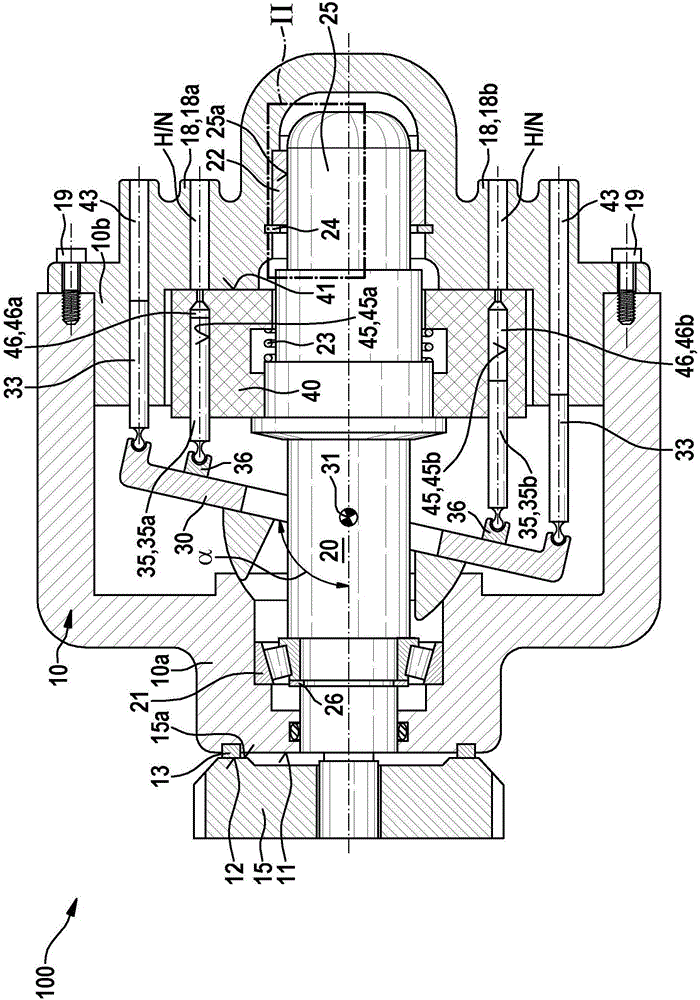
[0021] figure 1 A longitudinal section through an axial piston machine 100 is shown with a housing 10 consisting of a first housing part 10a and a second housing part 10b. The two housing parts 10 a and 10 b are screwed together by screws 19 .

[0022] In the housing 10, the drive shaft 20 is rotatably supported via two bearings:

[0023] - a first bearing 21, which is configured as a tapered roller bearing and is arranged in the first housing part 10a and

[0024] - A second bearing 22 , which is designed as a plain bearing and is arranged in the second housing part 10 b.

[0025] The second bearing 22 is arranged on the shaft end 25 of the transmission shaft 20 and cooperates with a bearing surface 25 a of the shaft end 25 .

[0026] The first securing ring 26 fixes the inner ring of the first bearing 21 configured as a tapered roller bearing relative to the shoulder of the transmission shaft 20 .

[0027] A second bearing 22 configured as a slide bearing is pressed into th


PUM

PropertyMeasurementUnit
Convexityaaaaaaaaaa

Abstract

An axial piston machine (100) for operation as a pump and/or motor, has a housing (10), a drive shaft (20) and a piston drum (40). The piston drum (40) is connected to the drive shaft (20). The drive shaft (20) is mounted rotatably within the housing (10) by means of a first bearing (21) and a second bearing (22), wherein the first bearing (21) is in the form of a tapered-roller bearing and the second bearing (22) is in the form of a plain bearing. The first bearing (21) can absorb axial forces on the drive shaft (20) in a force direction from the second bearing (22) toward the first bearing (21). The drive shaft (20) is preloaded in said force direction. On a housing face side (11), facing toward the drive input and/or output, of the housing (10), there is arranged an abutment surface (12) which can interact with a run-on surface (15a), facing the abutment surface (12), of a drive input or drive output wheel (15) arranged on the drive shaft (20).

Description


Claims


Application Information

Patent Timeline
Owner ROBERT BOSCH GMBH
Why Eureka
Try Eureka