Automatic spraying device applied to SPE film and achieving method of automatic spraying device

A technology of automatic spraying and realization method, applied in the direction of spraying device, spraying device, etc., can solve the problems affecting the uniformity of spraying, adding a large amount of dispersant, affecting the regularity of film formation, etc., to ensure uniformity and avoid uneven temperature distribution Uniformity, the effect of uniform thickness of the film

Active Publication Date: 2016-07-20
MATERIAL INST OF CHINA ACADEMY OF ENG PHYSICS
View PDF5 Cites 1 Cited by
  • Summary
  • Abstract
  • Description
  • Claims
  • Application Information

AI Technical Summary

Benefits of technology

This patented technology allows for better quality films made from sprayed or painted platy materials without causing any defects such as cracks during printing processes. It involves utilizing special equipment called a Sprayer Platform (SP), where a suction cup is placed near one end of the SP's opening. A tube connected through another hole create a low pressure area inside the SPVH while keeping other areas closed tight. By applying negative pressure at different locations within the space around the tungsten foam plate, there are tiny holes in its inner face allowing vaporized hydrogen atoms to escape into the atmosphere outside. These minute openings allow air molecules to enter the Titanium Plane Sheet instead of being absorbed completely. Additionally, the patents provide various technical featments like controlling the amount of energy supplied to the process, improving efficiency, stabilizes the system, and providing feedback signals to improve accuracy. Overall these improvements enhance the performance and effectiveness of producing thin films containing nanoporous particles.

Problems solved by technology

Technological Problem addressed by this patented technology describes various technical problem areas that require effective use of sophisticated techniques for producing thin films made from materials called ionomers or poly(methoxysulfonimide). These processes involve coating one side onto another easily removable support medium such as glass wires beforehand applying certain chemical reagents. Current methods are time-consuming, laborious, prone to variations caused by factors like pH levels and solvent evaporation rates. Additionally, there may also occur difficulties when replacing the catalysis layer due to sedimented particles formed after being deposited on top.

Method used


Image

  • Automatic spraying device applied to SPE film and achieving method of automatic spraying device
  • Automatic spraying device applied to SPE film and achieving method of automatic spraying device
  • Automatic spraying device applied to SPE film and achieving method of automatic spraying device

Examples


Embodiment Construction

[0046] The present invention will be further described below with reference to the accompanying drawings and embodiments, and the mode of the present invention includes but not limited to the following embodiments.

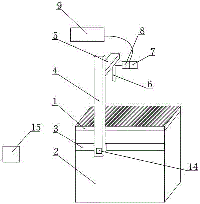
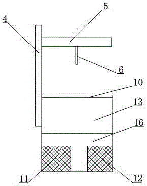
[0047] like figure 1 , 2 As shown, the present invention provides a novel SPE film automatic spraying device, which includes a cabinet 2, a guide rail 3, a catalyst temperature-controlled spraying device, a motor 14 and a PLC control system 15 connected with the motor 14.

[0048]The chassis 2 is divided into three layers from top to bottom, which are the spraying work platform 1, the vacuum chamber 13 and the equipment box 16 in turn, wherein the spraying work platform 1 is used to place the film fixture (for fixing the SPE film), and on the table A sintered porous titanium plate is provided, and an induction coil is evenly embedded in the table; a vacuum pump 12 for evacuating the vacuum chamber to form a negative pressure state and a vacuum pump 12 connected with


PUM


Abstract

The invention discloses an automatic spraying device applied to an SPE film and an achieving method of the automatic spraying device. The automatic spraying device comprises a case, a guide rail, a catalyst temperature control spraying device, a motor and a PLC control system. The case is provided with a spraying work platform, a vacuum chamber and an equipment box from top to bottom. The spraying work platform is used for containing a film clamp fixing the SPE film, a sintering porous titanium plate is arranged on the platform top of the spraying work platform, and an induction coil is evenly inlaid in the platform top. The equipment box is internally provided with a vacuum pump and a heating device connected with the induction coil. The guide rail is arranged on the side face of the case. The catalyst temperature control spraying device is in sliding connection with the guide rail and is used for spraying a catalyst to the SPE film. The motor is used for controlling the catalyst temperature control spraying device to move along the guide rail. The PLC control system is connected with the catalyst temperature control spraying device, the motor, the heating device and the vacuum pump at the same time. According to the automatic spraying device, the catalytic performance of the catalyst can be guaranteed, meanwhile, film swelling deformation of the SPE film is avoided, the film forming quality is improved, and the requirement for batched manufacturing is met.

Description


Claims


Application Information

Patent Timeline
Owner MATERIAL INST OF CHINA ACADEMY OF ENG PHYSICS
Why Eureka
Try Eureka