Fixing method of magnetic steel, rotor assembly and motor
A fixing method and technology of magnetic steel, applied in the direction of rotating parts of magnetic circuit, manufacturing stator/rotor body, electric components, etc., can solve the problems of weak bonding between magnetic steel and magnetic steel groove, slow curing speed of adhesive glue, etc. , to achieve the effect of shortening curing time, accelerating curing speed and fast curing
- Summary
- Abstract
- Description
- Claims
- Application Information
AI Technical Summary
Benefits of technology
Problems solved by technology
Method used
Image

Examples
Embodiment 1
[0052] This embodiment provides a method for fixing the magnetic steel, wherein, along the axial direction of the rotor core 1, the length of the magnetic steel groove 11 is greater than the length of the magnetic steel 2, including the following steps:
[0053] S1: Embed the magnetic steel 2 into the magnetic steel groove 11 of the rotor core 1, the two end faces of the magnetic steel groove 11 and the corresponding end faces of the two ends of the magnetic steel 2 respectively form inward concave grooves 6, preferably two The depth of each groove 6 is consistent, for example, the depth of groove 6 is preferably 1mm;
[0054] Inject the anaerobic adhesive 3 into the gap formed between the side wall surface of the magnetic steel 2 and the inner wall surface of the magnetic steel groove 11, for example, preferably Loctite 545 anaerobic adhesive, along the axial direction of the rotor iron core 1, the anaerobic adhesive applied The length of the oxygen glue 3 after the magnetic ste
Embodiment 2
[0068] This embodiment provides a fixing method for the magnetic steel 2. Compared with the fixing method for the magnetic steel 2 provided in Example 1, the only difference is that the step S1 is changed to: to the magnetic steel groove of the rotor core 1 The inner wall surface of 11 is coated with anaerobic adhesive 3, and then the magnetic steel 2 is embedded in the preset position in the magnetic steel groove 11.
[0069] For this fixing method, first coat the required anaerobic adhesive 3 in the magnetic steel groove 11, then insert the magnetic steel 2 into the magnetic steel groove 11, and then pour sealant on the end faces of the two ends of the magnetic steel 2 , so that a closed environment is formed in the magnetic steel groove 11, and the rapid solidification of the anaerobic adhesive 3 is promoted in the closed environment, and the magnetic steel 2 and the magnetic steel groove 11 are bonded and fixed.
[0070]As an alternative implementation of step S1, the step of
Embodiment 3
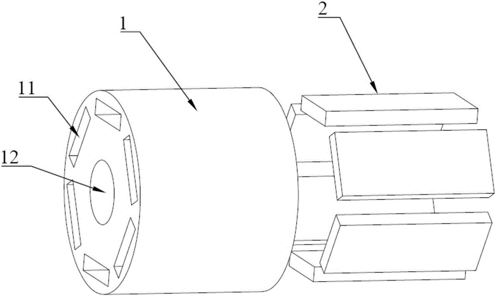
[0072] This embodiment provides a rotor assembly, such as figure 2 , image 3 and Image 6 As shown, it includes rotor core 1, magnetic steel 2, anaerobic adhesive 3 and two sealants. in,
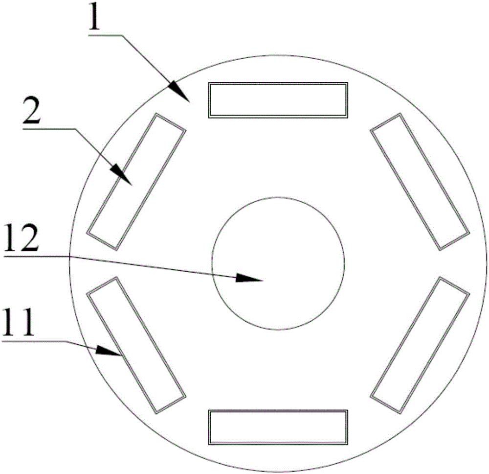
[0073] The rotor core 1 is formed with an inner hole 12 and six magnetic steel grooves 11 along its axial direction, and the six magnetic steel grooves 11 are symmetrically distributed around the outer circumference of the inner hole 12 on the circumferential end face of the rotor core 1;
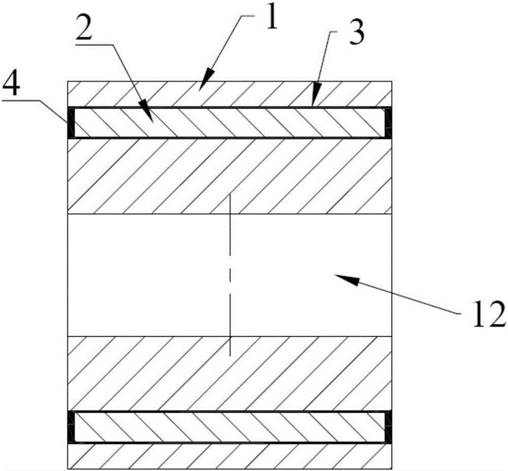
[0074] The magnetic steel 2 corresponds to the magnetic steel groove 11 one by one, and is suitable for being embedded in the magnetic steel groove 11. The length of the magnetic steel 2 is less than the length of the magnetic steel groove 11, and the end faces of the two ends of the magnetic steel groove 11 and the two ends of the magnetic steel 2 Inwardly recessed grooves 6 are respectively formed between the corresponding end faces, such as Figure 4 shown;
[0075] The anaerobic adhesive 3 is arra
PUM
 Abstract
Description
Claims
Application Information
 - R&D Engineer
- R&D Manager
- IP Professional
- Industry Leading Data Capabilities
- Powerful AI technology
- Patent DNA Extraction
Browse by: Latest US Patents, China's latest patents, Technical Efficacy Thesaurus, Application Domain, Technology Topic.
© 2024 PatSnap. All rights reserved.Legal|Privacy policy|Modern Slavery Act Transparency Statement|Sitemap