SLM powder recycling device

A recovery device and powder technology, which is applied in the field of additive manufacturing, can solve the problems of time-consuming and cumbersome steps, and achieve the effects of reducing environmental pollution, reducing powder waste, and improving powder screening efficiency

Active Publication Date: 2018-06-29
KUNMING UNIV OF SCI & TECH
View PDF11 Cites 2 Cited by
  • Summary
  • Abstract
  • Description
  • Claims
  • Application Information

AI Technical Summary

Problems solved by technology

[0003] Aiming at the problems existing in the prior art, the present invention provides a recovery device for SLM powder, which combines powder sieving, collection and drying processe

Method used


Image

  • SLM powder recycling device
  • SLM powder recycling device
  • SLM powder recycling device

Examples


Embodiment 1

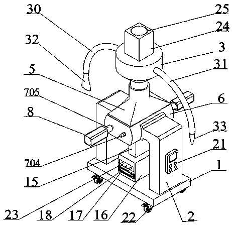
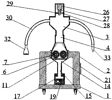
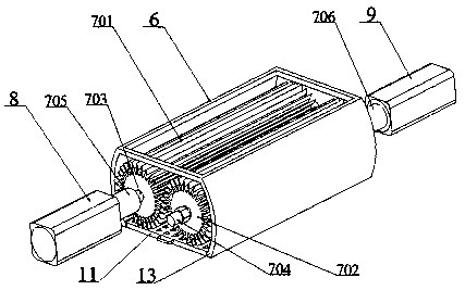
[0037] Embodiment 1: as Figure 1~9 As shown, a recovery device for SLM powder, including a base 1, two supporting columns 2, a powder falling chamber 3, a powder falling channel 4, a diffusion channel 5, a powder sieving chamber 6, and a rotating powder sieving scraper member 7 , screen 11, powder beam channel 14, powder collection channel 15, powder collection box 16, powder collection drawer 17, heating chamber 18, controller 21, 4 universal wheels 22, vacuum studio 24, powder suction pipe I30, Powder suction pipe Ⅱ31;

[0038] Four universal wheels 22 are respectively arranged on the four corners of the lower surface of the base 1, two support columns 2 are respectively arranged on both sides of the top of the base 1, and the powder sieving chamber 6 is fixedly arranged on the top of the support column 2 and outside the powder sieving chamber 6 The wall is connected with the ends of the two support columns 2, and the inner walls of the left and right sides of the bottom of t


PUM


Abstract

The invention relates to a SLM powder recycling device and belongs to the technical field of additive manufacturing. The recycling device comprises a base, two support pillars, a powder dropping chamber, a powder dropping channel, a diffusion channel, a powder screening chamber, rotary powder screening scraping piece components, a screening net, a powder constraining channel, a powder collection channel, a powder collection box, a powder receiving drawer, a heating chamber, a controller, four universal wheels, a vacuum working chamber, a powder suction pipe I and a powder suction pipe II. Thediffusion channel, the powder dropping channel, the powder dropping chamber and the vacuum working chamber are fixedly formed above the powder screening chamber in sequence. The lower portion of the powder screening chamber is fixedly provided with the powder constraining channel, the powder collection channel and the powder collection box in sequence. The powder receiving drawer is arranged inside the powder collection box. According to the SLM powder recycling device, the powder screening process, the powder recycling process and the powder drying process are of integrated design and implemented synchronously in a closed environment; no flying dust can be generated; the defects that steps are complex, and long time is consumed are overcome; and screening efficiency, recycling efficiencyand drying efficiency of powder are remarkably improved.

Description


Claims


Application Information

Patent Timeline
Owner KUNMING UNIV OF SCI & TECH
Why Eureka
Try Eureka