Non-contact energy and signal synchronous transmission system and transmission method

A signal synchronization and transmission system technology, applied in transmission systems, near-field transmission systems, electrical components, etc., can solve problems such as the influence of system energy transmission, low signal transmission rate, etc., to improve stability, reduce bit error rate, The effect of improving energy utilization

Active Publication Date: 2018-08-10
CHINA UNIV OF MINING & TECH
View PDF6 Cites 9 Cited by
  • Summary
  • Abstract
  • Description
  • Claims
  • Application Information

AI Technical Summary

Problems solved by technology

[0006] For the several energy and signal synchronous transmission methods proposed above, the signal transmission rate is generally relatively low, and it also has an impact on the system energy transmission

Method used


Image

  • Non-contact energy and signal synchronous transmission system and transmission method
  • Non-contact energy and signal synchronous transmission system and transmission method
  • Non-contact energy and signal synchronous transmission system and transmission method

Examples


Example Embodiment

Specific embodiment

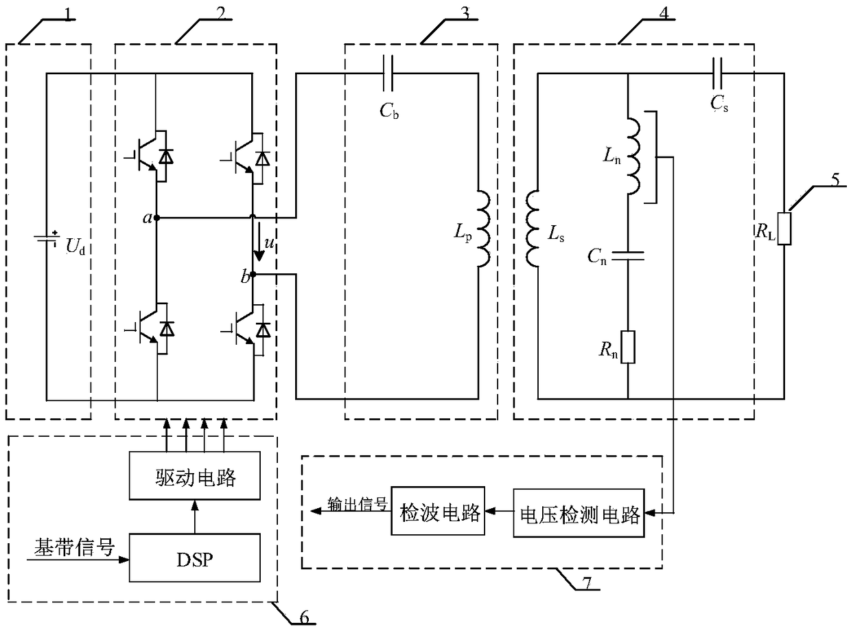
[0041] Such as figure 1 As shown, the DC power supply 1 generates a high-frequency AC voltage square wave after passing through the high-frequency inverter 2. When the inverter duty cycle is 50%, the inverted AC voltage square wave Fourier expression is

[0042]

[0043] Where U d Is the DC power supply voltage value, ω 0 The working angular frequency of the high frequency inverter, t is the time.

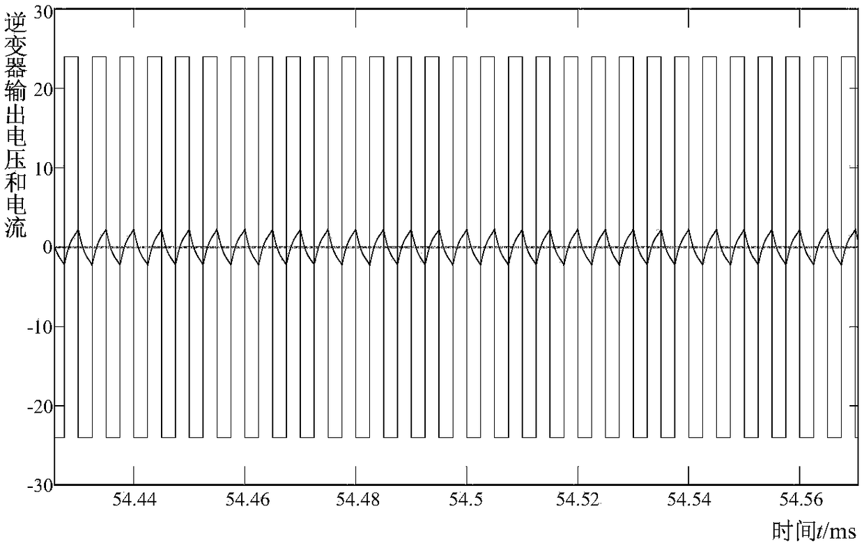
[0044] The high-frequency AC square wave voltage generates a triangular wave current after passing through the blocking capacitor and the transmitting coil.

[0045]

[0046] Where I pm Is the amplitude of the triangular wave current, and k is the harmonic order.

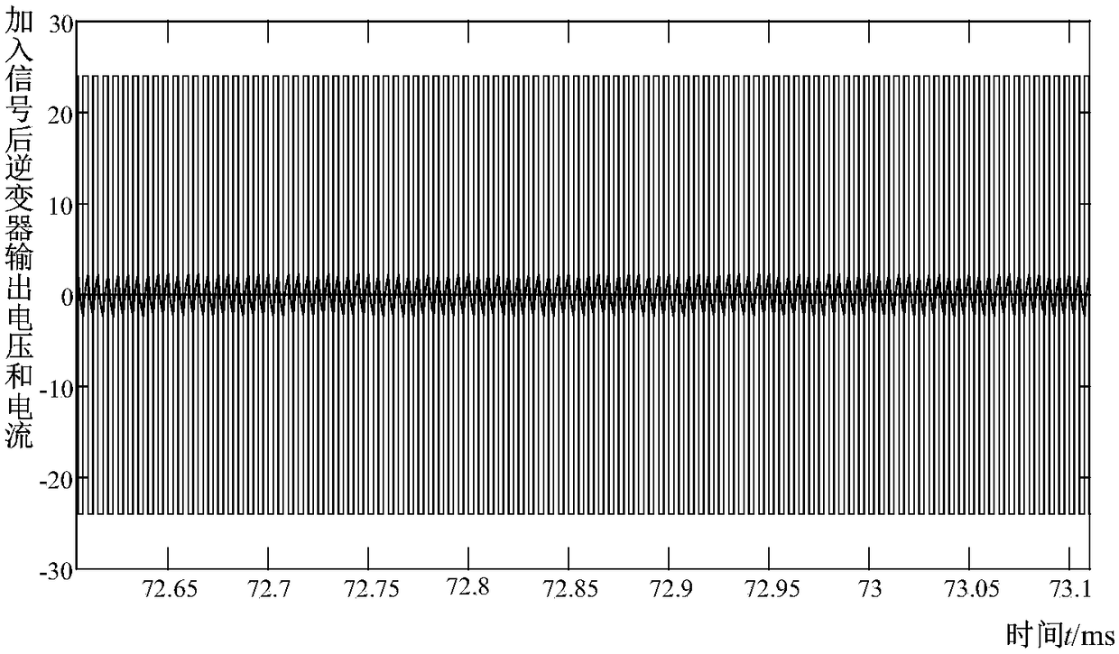
[0047] It can be seen from the above formula that the triangular wave current contains rich harmonics, so the fundamental wave is used to transmit energy and the harmonics to transmit signals. The triangular wave flows through the energy receiving part and the signal receiving part of the energy receiving mod


PUM


Abstract

The invention discloses an energy and signal synchronous transmission system and a transmission method in a wireless power transmission technology, which is applicable to the field of wireless charging. The system comprises a DC power supply, a high-frequency inverter, a primary-side energy transmitting module, a signal modulation module, a secondary-side energy receiving module, a signal demodulation module and a load, a blocking capacitor and the primary-side energy transmitting module are connected in series after the high-frequency inverter so as to form a triangular wave extraction channel; and the signal modulation module loads baseband signals to triangular waves through changing the operating frequency of the high-frequency inverter, the energy and signals are simultaneously transmitted to the secondary side through a loosely coupled transformer, the energy and the signals in the channel are separated through the secondary-side energy receiving module and the signal demodulation module, and synchronous transmission of the energy and the signals is realized. The non-contact energy and signal synchronous transmission system is stable in output power, high in signal transmission rate and small in system size.

Description


Claims


Application Information

Patent Timeline
Owner CHINA UNIV OF MINING & TECH
Why Eureka
Try Eureka