Turning and grinding tool for inner holes of bearing seat

A bearing seat and turning grinding technology, which is applied in the direction of grinding workpiece brackets, supports, positioning devices, etc., can solve the problems of insufficient machining accuracy of the inner hole, insufficient position, deformation of the workpiece, etc., and achieve simple structure, simple pressing method, The effect of increasing precision requirements

Pending Publication Date: 2018-10-02
无锡市万向联轴器有限公司
View PDF0 Cites 0 Cited by
  • Summary
  • Abstract
  • Description
  • Claims
  • Application Information

AI Technical Summary

Problems solved by technology

The high processing requirements of the parts make it difficult to fix and position the parts during production, especially in the process of turning the inner hole and grinding the inner hole, which will result in insufficient machining accuracy and insufficient position of the inner hole
[0003] There are also some tooling used for fi

Method used


Image

  • Turning and grinding tool for inner holes of bearing seat
  • Turning and grinding tool for inner holes of bearing seat
  • Turning and grinding tool for inner holes of bearing seat

Examples


Embodiment Construction

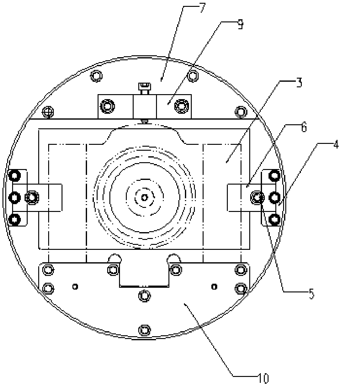
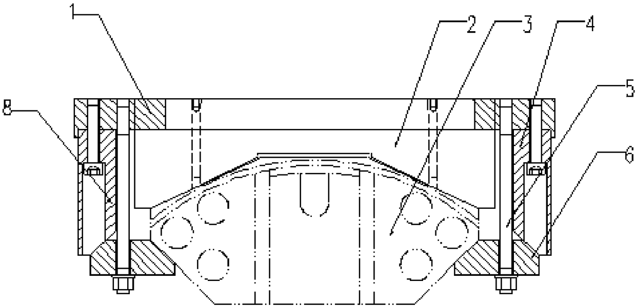
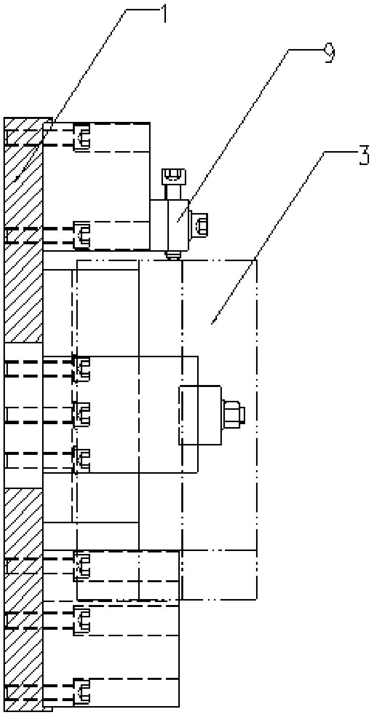
[0021] figure 1 It is a plan view of the present invention. figure 2 It is a front view of the present invention. image 3 It is the right side view of the present invention. set up figure 1 The two mutually perpendicular directions on the plane are the first direction and the second direction. set up figure 2 The two directions perpendicular to each other on the plane are the second direction and the third direction.

[0022] The bearing seat 3 is a workpiece installed in the tooling, one side of which is arc-shaped, and the other side has slope structures on both sides, which is the fourth slope.

[0023] Such as figure 1 , figure 2 , image 3 As shown, the present invention includes a coupling flange 1 . It also includes a V-shaped iron 2 fixed on the connecting flange 1. One side of the V-shaped iron 2 is close to the connecting flange 1, and the other side is a concave structure similar to a V shape, and its lowest point includes a plane, and the side of the pla


PUM


Abstract

The invention discloses a turning and grinding tool for inner holes of a bearing seat. The turning and grinding tool comprises a connecting flange plate, further comprises V-shaped iron fixed on the connecting flange plate, and further comprises a pressing plate. One side of the V-shaped iron is tightly attached to the connecting flange plate, and the other side of the V-shaped iron is provided with a V-shaped downward-sunken structure; the bearing seat is placed in the downward-sunken structure of the V-shaped iron; and the pressing plate is fixed to the connecting flange plate and fixes thebearing seat to the position between the V-shaped iron and the pressing plate. According to the turning and grinding tool, turning and grinding are adopted jointly, a bearing seat bulged key is reliedfor positioning, the slopes of the two sides of the bearing seat are relied to serve as compressing faces, in the machining process, the peripheries of the holes are not affected by clamping force and cutting force, and after the workpiece is unloaded, the bearing holes do not deform.

Description


Claims


Application Information

Patent Timeline
Owner 无锡市万向联轴器有限公司
Why Eureka
Try Eureka