High-screen duty cycle display device with fingerprint identification

A technology for fingerprint identification and display equipment, which is applied in branch office equipment, acquisition/organization of fingerprints/palmprints, character and pattern recognition, etc., which can solve inconvenience and other problems and achieve the effect of increasing the screen ratio

Active Publication Date: 2019-01-22
FOCALTECH ELECTRONICS
View PDF10 Cites 0 Cited by
  • Summary
  • Abstract
  • Description
  • Claims
  • Application Information

AI Technical Summary

Benefits of technology

This patented technology allows for better control over how much light goes through an electronic apparatus' screens compared to traditional displays without it being able to see them clearly. It also includes features like touch or force detection that help users interact more intuitively when they want their devices controlled differently from conventional controls. Overall this makes displaying large amounts of data easier than current methods while still maintaining good image quality.

Problems solved by technology

This patented technology improves how well people use their smartphones while having better accessibility when they are being used at different angles or positions compared to older models that had larger displays due to its front side featuring 5-8 inches diagonal screens instead of 4. However, there may be situations where it can happen if someone tries to tap them down too much without paying attention during these processes. To solve this problem, some existing designs have added a special area around each sensor location called a fingerprint sensation zone (FSZ) which helps prevent damage caused by excessive pressure applied through regular contact between users' hands and the sensitive components inside the phone itself.

Method used


Image

  • High-screen duty cycle display device with fingerprint identification
  • High-screen duty cycle display device with fingerprint identification
  • High-screen duty cycle display device with fingerprint identification

Examples


Embodiment Construction

[0038] In order to make the object, technical solution and advantages of the present invention clearer, the present invention will be further described in detail below in conjunction with the accompanying drawings and embodiments. It should be understood that the specific embodiments described here are only used to explain the present invention, not to limit the present invention.

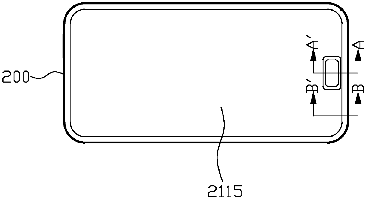
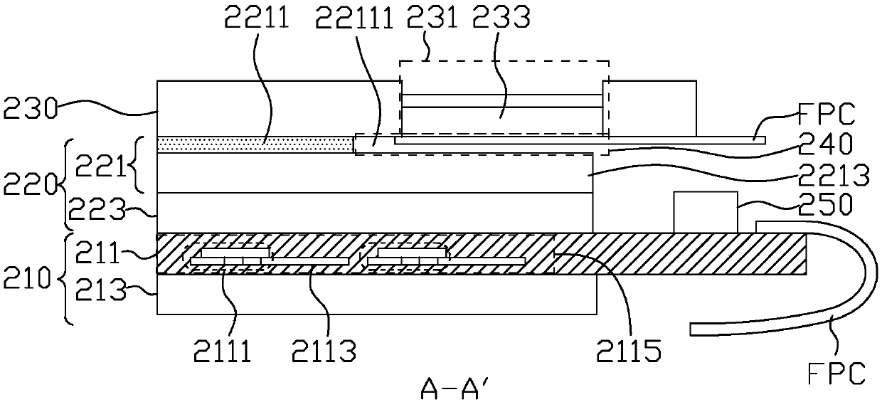
[0039] FIG. 2(A) is a schematic diagram of a first embodiment of a high screen-to-body ratio display device 200 with fingerprint recognition according to the present invention. FIG. 2(B) is a schematic cross-sectional view along line AA' in FIG. 2(A). FIG. 2(C) is a schematic cross-sectional view along line BB' in FIG. 2(A). Please refer to Figure 2(A) to Figure 2(C) , the high screen ratio display device 200 includes a lower substrate 210 , an upper substrate 220 , and a cover plate (CoverGlass) 230 .

[0040] The lower substrate 210 has a thin film transistor array layer (TFT array) 211 and a lo


PUM


Abstract

The invention provides a high-screen duty ratio display device with fingerprint identification, which comprises a lower substrate, an upper substrate and a cover plate. The lower substrate has a thinfilm transistor array layer provided with a plurality of thin film transistors and corresponding capacitors to provide a display area on the thin film transistor array layer. The upper substrate is located on one side of the thin film transistor array layer and has an optical film layer and a color filter layer. The cover plate is located on one side of the upper substrate, and has an aperture toreceive a fingerprint identification module, wherein the aperture of the cover plate is at least partially corresponding to the display area, and a space is formed below the aperture of the cover plate to receive a part of the fingerprint identification module.

Description


Claims


Application Information

Patent Timeline
Owner FOCALTECH ELECTRONICS
Why Eureka
Try Eureka