Gas filling device for wafer box and gas filling system

A filling system and filling device technology, applied in gas treatment, electrical components, transportation and packaging, etc., can solve the problems of reduced production efficiency, poor product yield, short longest waiting time, etc., to reduce wafer defects Probability of generation, effect of improving manufacturing yield

Inactive Publication Date: 2019-02-12
FOXSEMICON INTEGRATED TECHNOLOGY (SHANGHAI) INC +1
View PDF3 Cites 1 Cited by
  • Summary
  • Abstract
  • Description
  • Claims
  • Application Information

AI Technical Summary

Problems solved by technology

[0003] However, in the case of continuous shrinking of semiconductor process technology, the maximum allowable waiting time (Queue Time) from one process step to the next process step in the wafer process

Method used


Image

  • Gas filling device for wafer box and gas filling system
  • Gas filling device for wafer box and gas filling system
  • Gas filling device for wafer box and gas filling system

Examples


Embodiment Construction

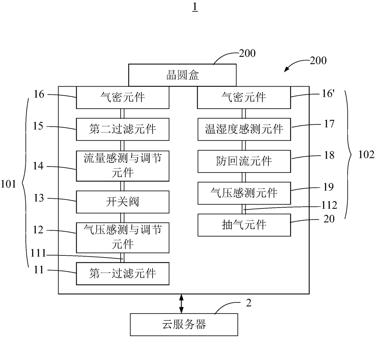
[0015] see figure 1 , a gas filling system 1 according to a preferred embodiment of the present invention includes a gas filling device 100 and a wafer cassette 200 connected to the gas filling device 100 .

[0016] The gas filling device 100 includes an inflatable component 101 and an exhaust component 102 . The inflatable component 101 is used for inflating the gas meeting the requirements of humidity and air pressure into the wafer cassette 200 when a trigger command is received. The gas pumping component 102 is used for pumping out the gas in the wafer box 200 when the gas filling component 101 starts filling the gas into the wafer box 200 , and detecting the humidity and temperature of the extracted gas.

[0017] In this embodiment, the gas filling device 100 communicates with a cloud server 2 via wire or wirelessly. The cloud server 2 is used to send the trigger command to the inflatable assembly 101 and the air extraction assembly 102 at the same time, thereby informing


PUM


Abstract

A gas filling system comprises a gas filling device and a wafer box connected with the gas filling device. The gas filling device comprises an inflation component and an exhaustion component, the inflation component is used for filling gas meeting humidity and air pressure requirements into the wafer box when a triggering instruction is received, and the exhaustion component is used for extractingthe gas in the wafer box when the inflation component starts to fill the gas into the wafer box and detecting humidity value and temperature value of extracted gas, and the humidity value and the temperature value of the gas correspond to a relative humidity value of the gas; when the relative humidity value of the gas is equal to a preset relative humidity value, the inflation component stops filling the water box, and the exhaust box stops gas extraction from the wafer box.

Description


Claims


Application Information

Patent Timeline
Owner FOXSEMICON INTEGRATED TECHNOLOGY (SHANGHAI) INC
Why Eureka
Try Eureka