Diode rectifier production system

A diode rectification and production system technology, applied in semiconductor/solid-state device manufacturing, electrical components, circuits, etc., can solve problems such as low production efficiency and quality, labor, consumption of more human resources, etc., to achieve high production efficiency and savings. Human resources, the effect of improving product yield and quality

Pending Publication Date: 2019-06-04
苏州旭芯翔智能设备有限公司
View PDF0 Cites 0 Cited by
  • Summary
  • Abstract
  • Description
  • Claims
  • Application Information

AI Technical Summary

Problems solved by technology

The diode rectifier device structure composed of two frames superimposed and welded with grains between the frames has become the mainstream of domestic diode and rectifier device production technology due to its high production efficiency, good quality and low cost, but the main production of the welding process is still through independent Equipment to complete, such as: printing solder paste on t

Method used


Image

  • Diode rectifier production system
  • Diode rectifier production system
  • Diode rectifier production system

Examples


Embodiment Construction

[0025] The technical solution of the present invention will be described in further non-limiting detail below in combination with preferred embodiments and accompanying drawings.

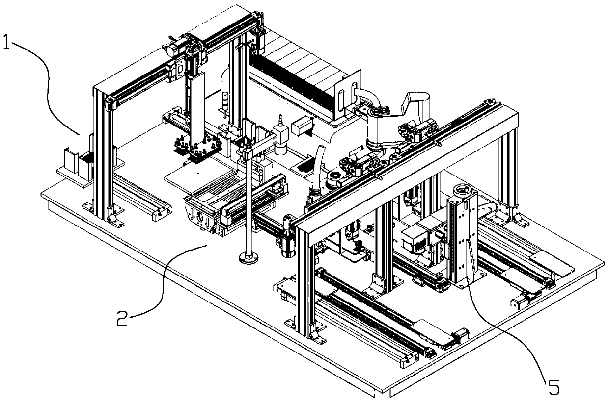
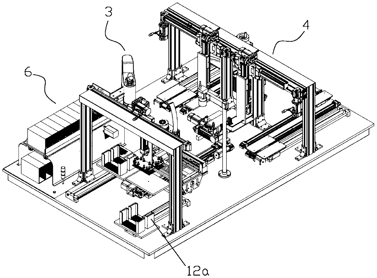
[0026] A kind of diode rectifier device production system, diode rectifier device comprises frame and is welded on frame and is crystal grain, and frame comprises upper frame 71 and lower frame 72 (such as Figure 6 and Figure 7 shown), before the production of the diode rectifier device starts, the upper frame 71 and the lower frame 72 are stored in the placing frame 12a (as figure 2 shown), the crystal grains are stored in the grain shaking plate 73 (as Figure 8 shown).

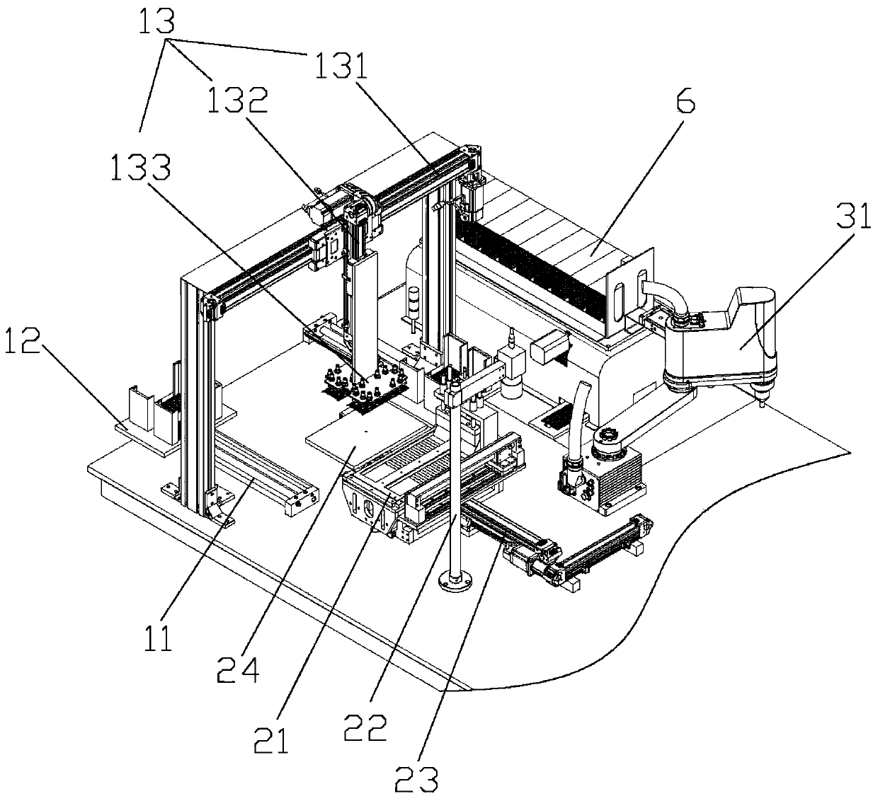
[0027] like figure 1 and figure 2 As shown, the diode rectifier device production system includes a feeding unit 1 for feeding the frame, a welding unit 5 for welding the frame, a printing unit 2 connected to the feeding unit 1 for printing solder paste on the frame, A fixing unit 4 connected to the soldering unit 5 for fix


PUM


Abstract

The invention discloses a diode rectifier production system. A diode rectifier comprises a frame and crystal grains welded to the frame. The diode rectifier production system comprises a feeding unit(1) for feeding the frame, a welding unit (5) for welding the frame, a printing unit (2) connected with the feeding unit (1) and used to printing the frame with a solder paste, a fixing unit (4) connected with the welding unit (5) and used to fix the crystal grains on the frame, and a transport unit (3) arranged between the solder paste printing unit (2) and the fixing unit (4) and used to transport the frame. The diode rectifier production system can product the diode rectifier automatically, labor resources are saved, and the production efficiency is improved.

Description


Claims


Application Information

Patent Timeline
Owner 苏州旭芯翔智能设备有限公司
Why Eureka
Try Eureka