High-temperature printing and dyeing waste gas treatment equipment

A waste gas treatment equipment and high-temperature technology, applied in lighting and heating equipment, air quality improvement, liquid separation agent, etc., can solve problems such as bad smell, thick smoke, material consumption, pollution, etc., to improve treatment efficiency and increase Effect of contact area, ability to raise

Pending Publication Date: 2019-09-24
SUZHOU BANGTIKE INTELLIGENT TECH CO LTD
View PDF3 Cites 0 Cited by
  • Summary
  • Abstract
  • Description
  • Claims
  • Application Information

AI Technical Summary

Benefits of technology

This patented technology describes different ways for treating high-quality printed or dyed materials by removing unwanted substances from them during production processes such as thermal printing (hot offset) or dying techniques. It achieves this by utilizing multiple stages of filters, cyclones, vaporizers, and bubble traps before being released into atmosphere. By separating these components based on their properties, harmful gases like oily smoke, greasy mist, volatile organic compounds, nitrogen oxide, sulfur dioxides, hydrocarbon chlorine, formaldehydes, methane, ethanol, acetone, benzene, phenols, ammonia, peroxyacids, uranium, radon, chromate, lead, mercury, selenium, polytetrafluoroethylene, polyvinyl alcohol, silicate glass fibers, plasma display screens, lithography masks, electronic devices, batteries, electric motors, sensory organs, medical implants, biological samples, food products, chemical reactions, metal manufacturing, machinery, automobiles, trucks, ships, space vehicles, military systems, nuclear power plants, environmental protection organizations, governmental agencies, regulators, and other industries involved in various industrial activities where highly sensitive areas require strict regulations regarding contamination levels.

Problems solved by technology

The technical problem addressed by this patented technology relates to disposal or recycling these wastes without causing harmful effects on human body, animals, plants, bioresearchers, wildlife, etc., especially when there are heavy metals like mercury that may have negative impact upon humans' physical well-beings such as skin damage caused through contact between them during use for various applications (text describes examples).

Method used


Image

  • High-temperature printing and dyeing waste gas treatment equipment
  • High-temperature printing and dyeing waste gas treatment equipment
  • High-temperature printing and dyeing waste gas treatment equipment

Examples


Embodiment

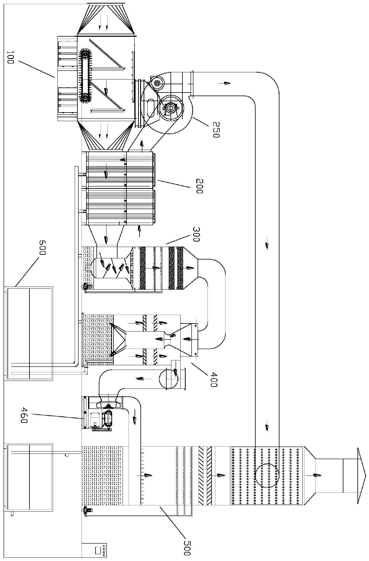
[0043] In the process of textile printing and dyeing, waste gas containing fluff, particulate matter, lampblack, wax, VOCs and other mixtures will be discharged, and it has the characteristics of high temperature, high humidity and strong adhesion, which is difficult to deal with. Aiming at this technical problem, the present invention discloses a high-temperature printing and dyeing waste gas treatment equipment, which includes a multi-stage filter device 100, a gas-gas heat exchange device 200, a swirl tower 300, a Venturi scrubber 400, and an active mud scrubber 500, and an oil dust collection pool 600.

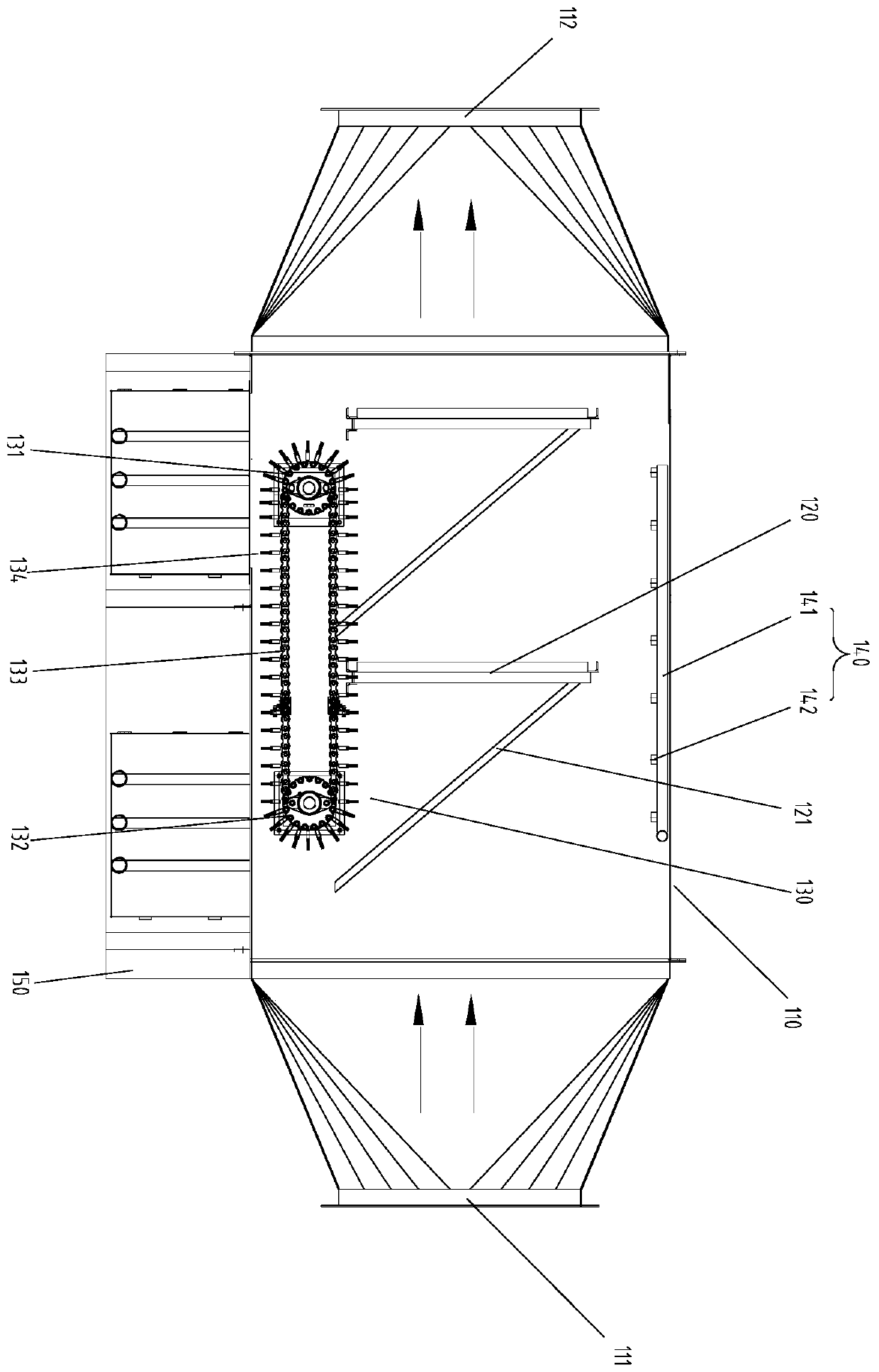
[0044] The multi-stage filter device 100 is the first equipment through which exhaust gas passes. see Figure 1-2 , which includes a filter housing 110, one end of the filter housing 110 is provided with an exhaust gas inlet 111, and the other end is provided with an exhaust gas inlet 112, and the filter housing 110 has an air duct for exhaust gas to pass through. A deconta


PUM


Abstract

The invention discloses high-temperature printing and dyeing waste gas treatment equipment. The equipment comprises a multi-stage filtering device, a gas-gas heat exchange device, a rotational flow tower, a Venturi scrubbing tower and an active mud washing tower which are communicated in sequence; the Venturi scrubbing tower comprises a washing tower body, wherein the top of the Venturi scrubbing tower is provided with an opening, the side wall of the Venturi scrubbing tower is provided with an outlet, and the outlet is connected with an exhaust fan; the washing tower body is internally provided with cleaning liquid, and is provided with a Venturi tube, and an inlet of the Venturi tube is connected to the top opening and is used for introducing waste gas treated by the rotational flow tower; the pipework of the Venturi tube is connected with a conical oblique nozzle, and the tail end of the conical oblique nozzle is inserted under the liquid surface; the waste gas passes through the pipework of the Venturi tube to form a high-speed airflow, and tangentially enters the portion, under the liquid surface, in the tower body through the conical oblique nozzle to form a large number of microbubbles, and the microbubbles are in full contact with the cleaning liquid to remove soot and particulate matter in the waste gas. The high-temperature printing and dyeing waste gas treatment equipment can process the waste gas of the printing and dyeing process efficiently and stably at low cost.

Description


Claims


Application Information

Patent Timeline
Owner SUZHOU BANGTIKE INTELLIGENT TECH CO LTD
Why Eureka
Try Eureka