OLED display panel

A technology for display panels and display areas, applied in the field of OLED display panels, can solve the problems of different fluidity of thin-film encapsulation organic layers, failure of organic film encapsulation, and different surface topography of inorganic/metal film layers, etc., so as to prolong the service life. , Improve the uniformity of film formation and improve the effect of fluidity

Active Publication Date: 2020-04-10
WUHAN CHINA STAR OPTOELECTRONICS SEMICON DISPLAY TECH CO LTD
View PDF5 Cites 2 Cited by
  • Summary
  • Abstract
  • Description
  • Claims
  • Application Information

AI Technical Summary

Benefits of technology

The technical effect that these inventions provide for better control over how well liquid crystal material fills up between two electrodes on top of each other during operation. By arranging multiple channels along certain lines around specific areas within the screen's borders or walls, it becomes easier to evenly distribute the filling process throughout all parts of the device while also allowing more space inside them without compromising their function properly.

Problems solved by technology

This patented technical problem addressed by this patents describes how to protect and package electronic displays from moisture and oxidation while maintaining good optics performance without compromising any desired properties such as bright colors and reduced resolution caused by bending.

Method used


Image

  • OLED display panel
  • OLED display panel
  • OLED display panel

Examples


Embodiment Construction

[0025] The technical solutions in the embodiments of the present application will be clearly and completely described below in conjunction with the drawings in the embodiments of the present application. Obviously, the described embodiments are only a part of the embodiments of the present application, rather than all the embodiments. Based on the embodiments in this application, all other embodiments obtained by those skilled in the art without creative work shall fall within the protection scope of this application.

[0026] In the description of this application, it should be understood that the terms "center", "longitudinal", "transverse", "length", "width", "thickness", "upper", "lower", "front", " "Back", "Left", "Right", "Vertical", "Horizontal", "Top", "Bottom", "Inner", "Outer", "Clockwise", "Counterclockwise" and other directions or The positional relationship is based on the orientation or positional relationship shown in the drawings, and is only for the convenience of


PUM


Abstract

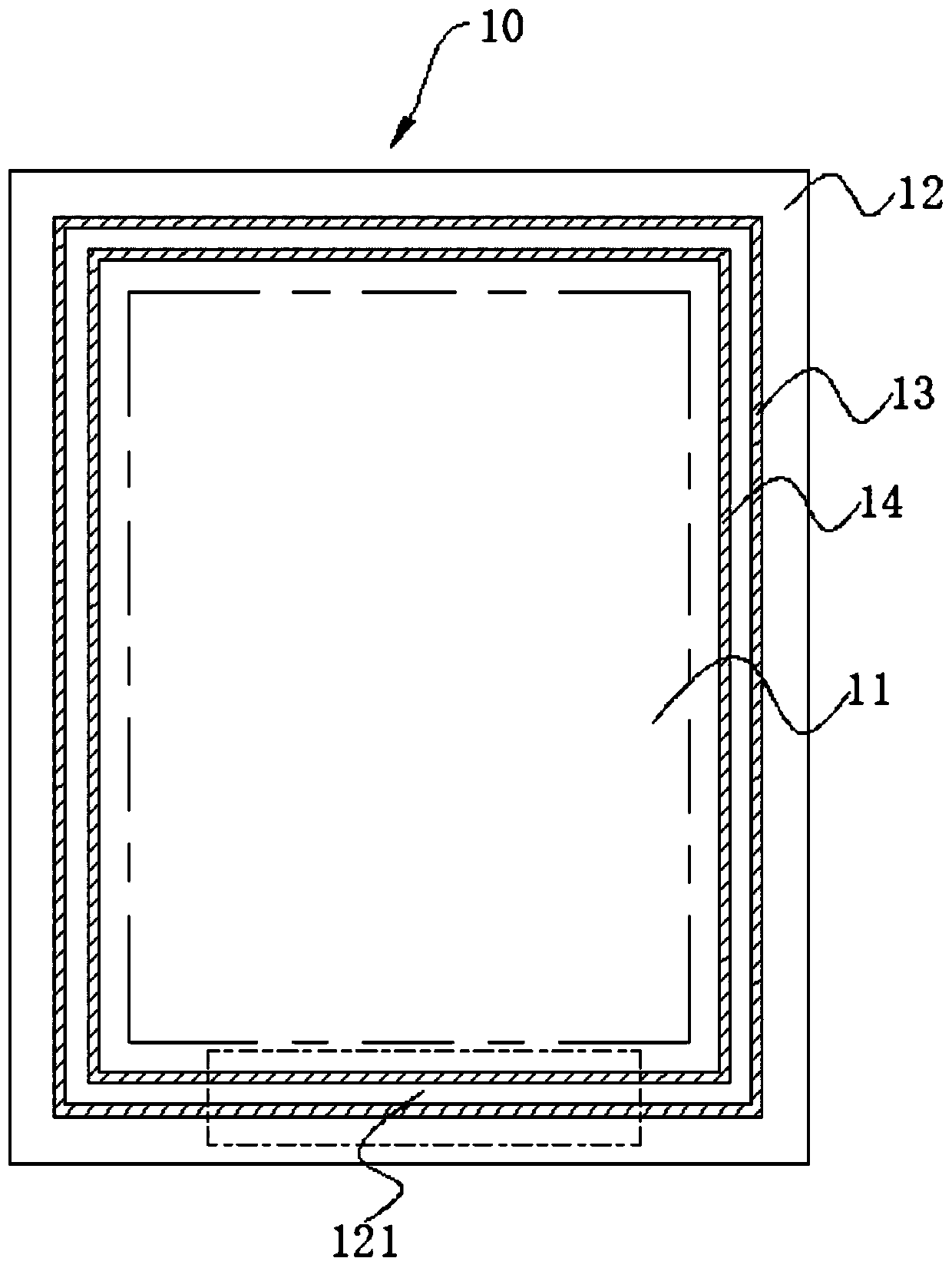
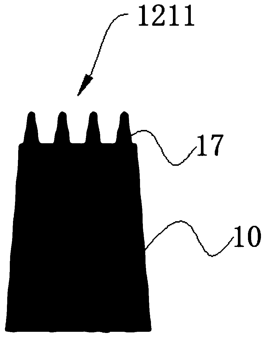
The invention discloses an OLED display panel which comprises a display area and a non-display area and further comprises an array substrate, a first retaining wall, a second retaining wall, a plurality of metal routings, a plurality of first grooves and a thin film packaging layer, wherein the metal routing layer is located in a fan-out routing area, close to a lower frame, of the array substrate, part of the metal routings are arranged along the direction perpendicular to the first retaining wall, and the included angle between the other part of the metal routings and the first retaining wall is an acute angle; the plurality of first grooves are arranged in the fan-out routing area and are arranged along the direction of the metal routings; the part, corresponding to the second area, ofthe array substrate is further provided with a plurality of second grooves, and the second grooves are distributed along the direction perpendicular to the first retaining wall.

Description


Claims


Application Information

Patent Timeline
Owner WUHAN CHINA STAR OPTOELECTRONICS SEMICON DISPLAY TECH CO LTD
Why Eureka
Try Eureka