Quick butt joint assembly and quick butt joint mechanism

A technology for docking components and docking mechanisms, which is applied to structural elements, building components, building structures, etc., can solve the problem that the base and the second embedded component are prone to misalignment, and it is difficult to determine the relative position of the base and the second embedded component. relationship, safety hazards and other issues, to achieve the effect of shortening construction time, simple installation, and improving tensile performance

Pending Publication Date: 2020-04-21
许顺良
View PDF0 Cites 0 Cited by
  • Summary
  • Abstract
  • Description
  • Claims
  • Application Information

AI Technical Summary

Problems solved by technology

Before the quick docking assembly is used, the base in the quick docking assembly needs to be installed in the second embedded assembly in the quick docking mechanism, but it is currently difficult to determine the relative positional relationship between the base and the second embedded assembly; and When the quick docking components are docked, the force direction is perpendicular to the ground, and the base and the second pre-embedded component are both subjected to vertical downward force. At present, the vertical downward force that the two can withstand after mating Smaller, the base and the second pre-embedded component are prone to misalignment and other problems, posing safety hazards

Method used


Image

  • Quick butt joint assembly and quick butt joint mechanism
  • Quick butt joint assembly and quick butt joint mechanism
  • Quick butt joint assembly and quick butt joint mechanism

Examples


Embodiment Construction

[0037] The following will clearly and completely describe the technical solutions in the embodiments of the present invention with reference to the accompanying drawings in the embodiments of the present invention. Obviously, the described embodiments are only some, not all, embodiments of the present invention. Based on the embodiments of the present invention, all other embodiments obtained by persons of ordinary skill in the art without making creative efforts belong to the protection scope of the present invention. As used herein, the term "or / and" includes any and all combinations of one or more of the associated listed items.

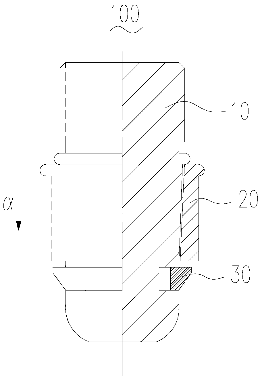
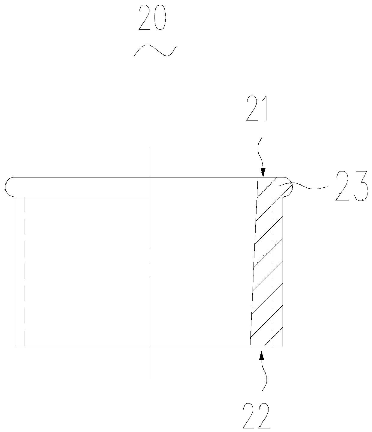
[0038] see figure 1 , figure 1 It is a schematic structural diagram of the base 20 in an embodiment of the present invention.

[0039] The present invention provides a quick docking assembly 100 for connecting two engineering parts. In this embodiment, the quick docking assembly 100 is used to connect the steel bar 310 in the concrete prefabric...


PUM

PropertyMeasurementUnit
Heightaaaaaaaaaa

Abstract

The invention provides a quick butt joint mechanism. The quick butt joint mechanism comprises an inserting table, a base and a ring buckle, wherein the inserting table comprises a fixed part and an inserting part which are oppositely arranged, and the inserting part is provided with a first groove; the base is provided with a first end face and a second end face which are oppositely arranged; thering buckle is provided with an opening and can elastically contract, and the ring buckle is arranged on the inserting table in a sleeve mode and is accommodated in the first groove; the ring buckle can be inserted into the base in the inserting direction together with the inserting part of the inserting table, and the ring buckle can abut against the second end face of the base through elastic expansion, and limits the reverse movement of the inserting table in the inserting direction; the base is provided with a second boss, and the second boss is used for positioning the relative positionalrelationship between the base and a second embedded assembly in the quick butt joint mechanism. According to a quick butt joint assembly provided by the invention, the relative position relationshipbetween the base and the second embedded assembly is rapidly determined through the second boss, and the phenomena of dislocation and the like generated after the joint between the second embedded assembly and the base is stressed can be avoided.

Description

technical field [0001] The invention relates to the technical field of construction, in particular to a quick docking assembly and a quick docking mechanism. Background technique [0002] In the field of construction technology, in order to facilitate production and processing and reduce construction time, the length of prefabricated piles is often guaranteed by combining reinforced concrete prefabricated piles. In order to quickly and firmly connect two reinforced concrete prefabricated piles, a quick butt joint assembly is generally used to connect the steel bars inside the two reinforced concrete prefabricated piles. Before the quick docking assembly is used, the base in the quick docking assembly needs to be installed in the second embedded assembly in the quick docking mechanism, but it is currently difficult to determine the relative positional relationship between the base and the second embedded assembly; and When the quick docking components are docked, the force d...

Claims


Application Information

Patent Timeline
IPC IPC(8): E02D5/30E02D5/52E04C5/16
CPCE02D5/30E02D5/526E04C5/162
Inventor 许顺良
Owner 许顺良
Why Eureka
Try Eureka