Herringbone tooth cutting method for servo control compensation

A cutting method and servo control technology, which is applied in the direction of program control, computer control, general control system, etc., can solve the problems of high scrap rate and difficult operation of initial cutting herringbone teeth, so as to shorten the manufacturing cycle and save labor costs , Improve the effect of cutting accuracy

Pending Publication Date: 2020-09-25
CHONGQING MACHINE TOOL GROUP
View PDF0 Cites 1 Cited by
  • Summary
  • Abstract
  • Description
  • Claims
  • Application Information

AI Technical Summary

Problems solved by technology

[0002] A hob is used to process herringbone teeth on a large-scale CNC gear hobbing machine. Since the machining accuracy of herringbone teeth is affected by factors such as machine tool geometry accuracy, machine rigidity, cutting parameter settings, and fixture system accuracy, and the center of the left and right tooth faces of the herringbone teeth is Using the traditional fitter scribing hobbing gear alignment processing method, this processing method must be accurate scribing, precise tool setting, and experience correction, which is difficult for the operator of the initial cutting herringbone gear, and the scrap rate is high

Method used


Image

  • Herringbone tooth cutting method for servo control compensation
  • Herringbone tooth cutting method for servo control compensation

Examples


Example Embodiment

[0026] The preferred embodiments of the present invention will be described in detail below with reference to the accompanying drawings. It should be understood that the preferred embodiments are only for illustrating the present invention, not for limiting the protection scope of the present invention.

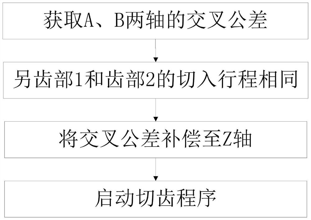
[0027] The present invention proposes a servo-controlled and compensated herringbone tooth cutting method. The method is summarized as: obtaining the AB axis cross tolerance through testing, and then optimizing the cutting parameters, that is, ensuring the feed stroke of the herringbone tooth 1, tooth 2 gear It is the same, and the AB axis cross tolerance is compensated to the Z axis control in the numerical control system, and finally achieves a smaller herringbone tooth centering tolerance and improves herringbone tooth cutting accuracy.

[0028] Specific, such as figure 1 Shown.

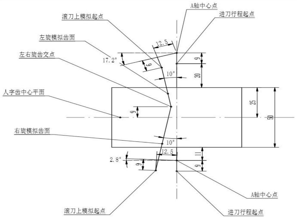
[0029] S1: Due to the cross tolerance of the AB axis and AC axis of the machine tool, the starting poi


PUM


Abstract

The invention discloses a herringbone tooth cutting method for servo control compensation. The cutting method specifically comprises the steps that the cross tolerance of an A axis and a B axis of a numerical control gear hobbing machine tool in a static state is obtained; the cutting strokes of a tooth part 1 and a tooth part 2 of a tooth cutting test blank adopt the same value and input into a tooth cutting program; the cross tolerance is compensated to a Z axis; and the tooth cutting program is started. The herringbone tooth centering tolerance caused by machine tool precision and cutting machining is reduced, the herringbone tooth cutting precision is improved, the production and manufacturing period of a machine tool is indirectly shortened, and the labor cost is saved.

Description


Claims


Application Information

Patent Timeline
Owner CHONGQING MACHINE TOOL GROUP
Why Eureka
Try Eureka