Traction device of material station for belt material processing

A pulling device and material technology, applied in the field of belt material processing and forming equipment, can solve the problems of high labor intensity, hidden danger of manual pulling, and low efficiency, and achieve the effects of reducing production cost, improving production efficiency, and facilitating pulling operation.

Pending Publication Date: 2020-11-10
HENAN XINZHILIN ELECTROMECHANICAL DEVICE CO LTD
View PDF0 Cites 0 Cited by
  • Summary
  • Abstract
  • Description
  • Claims
  • Application Information

AI Technical Summary

Benefits of technology

This patented technology allows for efficient manufacturing processes with improved productivity while reducing cost compared to traditional methods such as manually cutting up each piece of raw sheet before it goes into another process. It achieves this by moving a pivot arm mechanism called the swing arms around a frame system, allowing the newly formed pieces of paper to be moved together during processing. A specialized machine tool then applies pressure onto these sheets to bond them securely. By doing this, there will be no extra steps needed when producing different types of products. Overall, this innovative method improves efficiency and reduces costs associated with existing methods like hand sewing machines used for making labels.

Problems solved by technology

This patented technical problem addressed by this patents relates to improving the safe and efficient way to feed strips into an autoamtic machine during manufacturing processes that require continuous or intermittently wound metal tubes called cigarettage wrappers (CCs). Current methods involve manually attaching these coupons onto the machines' drums with adhesive glue, which requires skilled workers who have special training and experience. There may exist concerns over potential health risks associated with human error due to incorrect placement of coupon slivers.

Method used


Image

  • Traction device of material station for belt material processing
  • Traction device of material station for belt material processing
  • Traction device of material station for belt material processing

Examples


Embodiment Construction

[0024] The present invention will be further described in detail below in conjunction with the accompanying drawings.

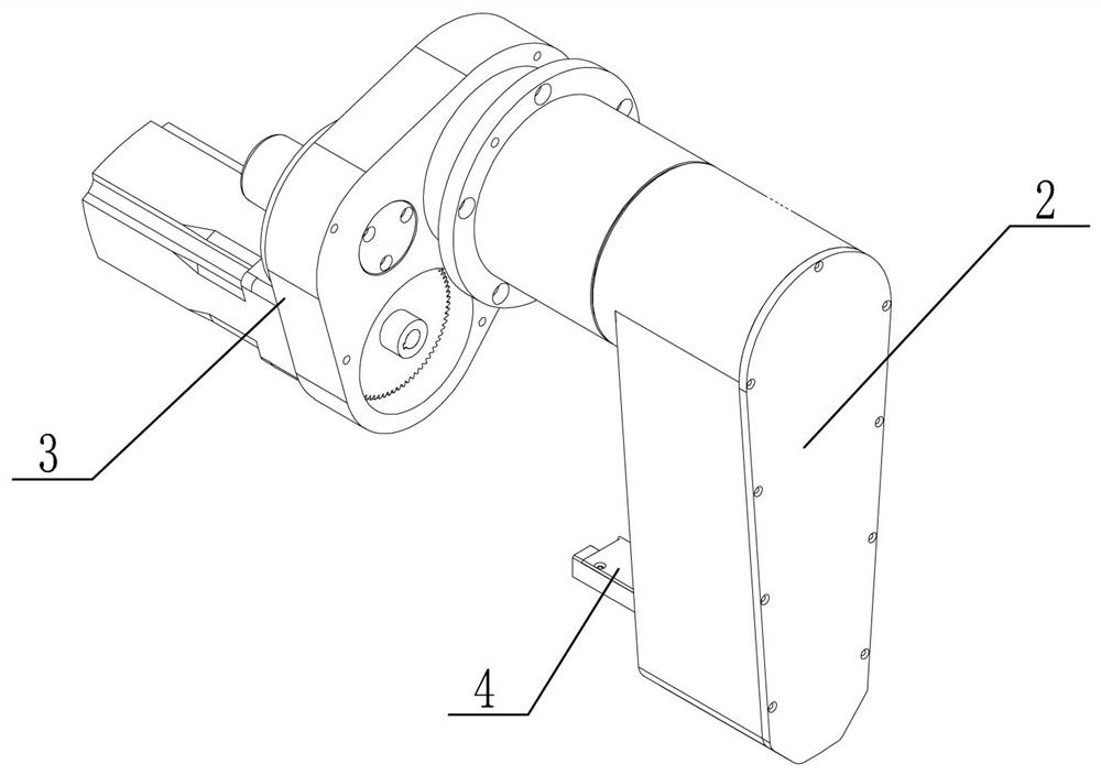
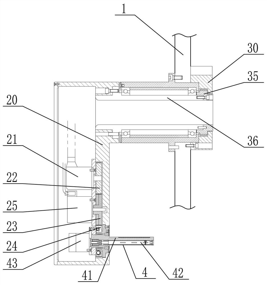
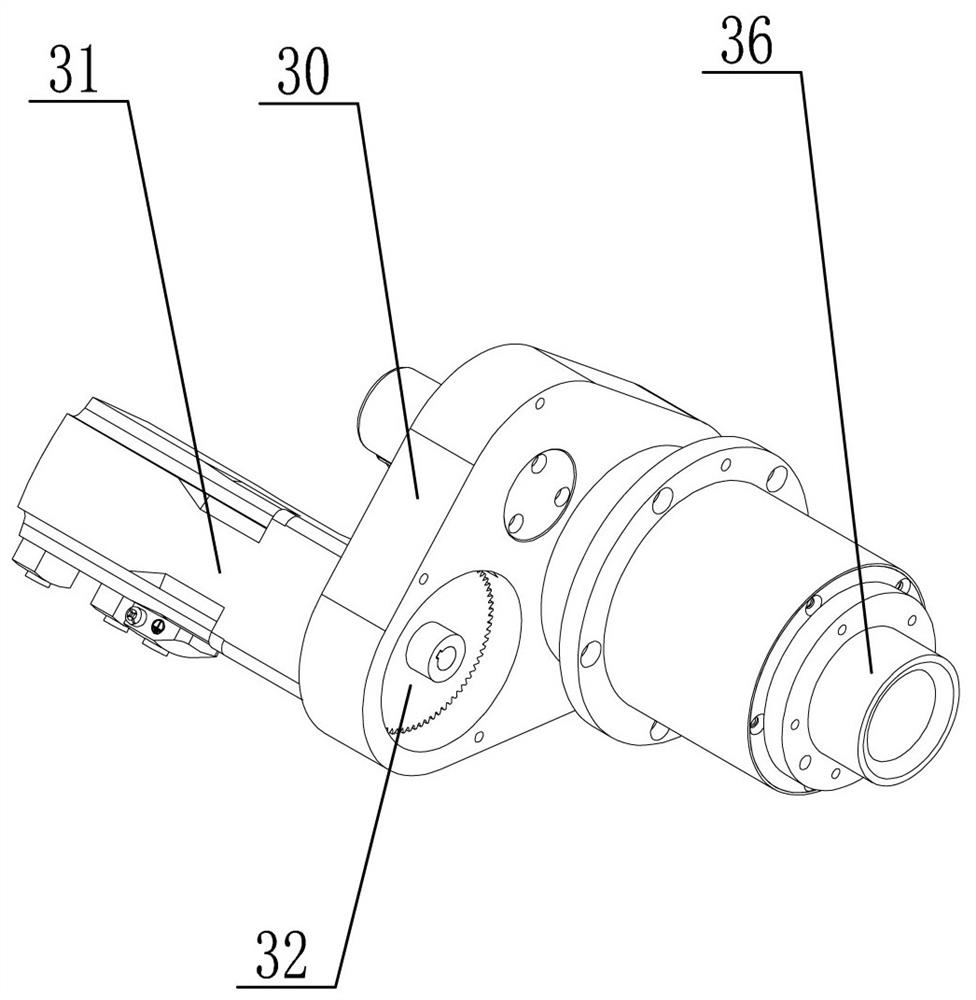
[0025] Such as figure 1 , figure 2 , image 3 , Figure 4 , Figure 5 and Figure 6As shown, a material traction device for strip-shaped material processing includes a main vertical plate 1, a swing arm mechanism 2 and a driving mechanism 3, and the main vertical plate 1 is vertically arranged to support the swing arm mechanism 2 and the driving mechanism 3. The driving mechanism 3 is arranged on the rear end surface of the main vertical plate 1, and the output shaft 36 of the driving mechanism 3 passes through the main vertical plate 1 and is connected with the swing arm mechanism 2 located at the front end surface of the main vertical plate 1. The driving mechanism 3 To provide power for the swing of the swing arm mechanism 2, the swing arm mechanism 2 includes a swing arm housing 20, an angle adjustment motor 21, an angle driving gear 22, an angle inter


PUM


Abstract

The invention provides a traction device of material station for belt material processing. According to the traction device, a driving mechanism is utilized for driving a swinging arm mechanism to swing, so that a clamping jaw assembly arranged in the swinging arm mechanism can move among an adhesive receiving station, a splicing station and a new material tray starting-up station; at the new material tray starting-up station, the clamping jaw assembly clamps the belt head of a new belt material; and consequently, the preparation for the automatic splicing of the belt head of the new belt material and the tail section of an old belt material can be achieved, no manual operation is needed, the production efficiency can be effectively improved, and the production cost can be reduced.

Description


Claims


Application Information

Patent Timeline
Owner HENAN XINZHILIN ELECTROMECHANICAL DEVICE CO LTD
Why Eureka
Try Eureka