High-performance copper alloy and preparation method thereof
A copper alloy, high-performance technology, applied in metal material coating process, fusion spraying, coating, etc., can solve the problems of poor high temperature resistance, poor strength, etc., achieve good electrical conductivity, improve high temperature resistance, improve resistance Effect of High Temperature Properties and Strength
- Summary
- Abstract
- Description
- Claims
- Application Information
AI Technical Summary
Problems solved by technology
Method used
Image

Examples
Example Embodiment
[0027] A method for preparing a high-performance copper alloy, comprising the steps of:
[0028] step one:
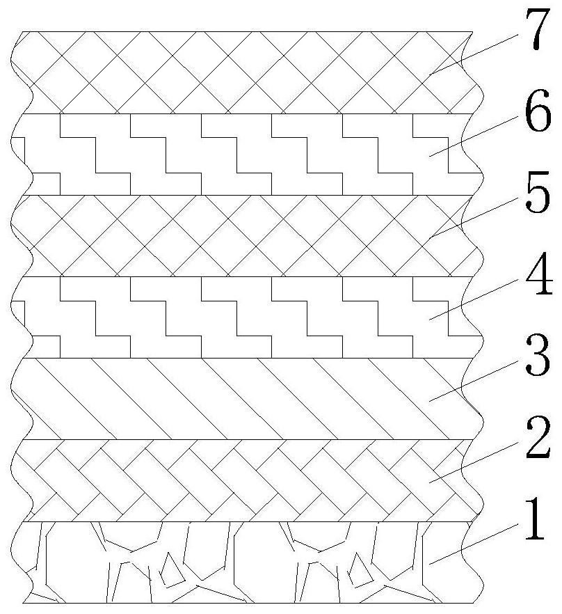
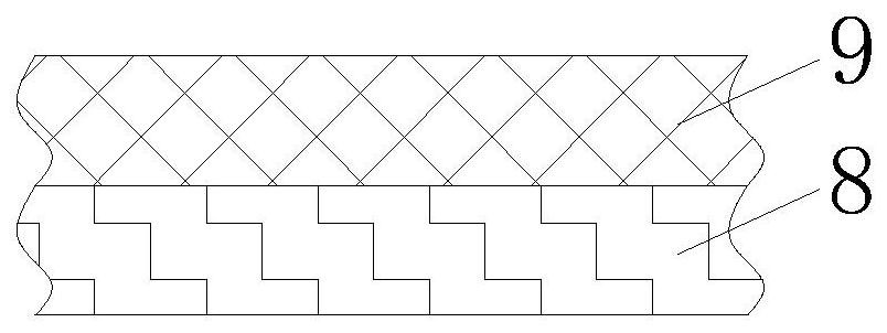
[0029] The nickel-copper alloy layer 9 is deposited on the surface of the brass alloy layer 8 by the HVOF method, and then the base layer 1 formed by the brass alloy layer 8 and the nickel-copper alloy layer 9 is polished, degreased by electrocleaning, activated and post-treated.
[0030] Step two:
[0031] Using the HVOF method to deposit the intermediate layer 2 on the surface of the base layer 1 formed by the brass alloy layer 8 and the nickel-copper alloy layer 9 obtained in step 1, and depositing the tungsten alloy layer 3 on the surface of the intermediate layer 2 by using the HVOF method.
[0032] Step three:
[0033] A ceramic material layer 4 is deposited on the surface of the tungsten alloy layer 3 obtained in step 2 by using the HVOF method, and then a white graphene layer 5 is deposited on the surface of the ceramic material layer 4 by a brushing method.
[
Example Embodiment
[0036] Embodiment one:
[0037] Utilize the HVOF method to deposit a nickel-copper alloy layer 9 on the surface of the brass alloy layer 8, and then the base layer 1 formed by the brass alloy layer 8 and the nickel-copper alloy layer 9 is polished, electrically degreased, activated, and post-treated. The HVOF method deposits an intermediate layer 2 on the surface of the base layer 1 formed by the brass alloy layer 8 and the nickel-copper alloy layer 9 obtained in step one, and utilizes the HVOF method to deposit a tungsten alloy layer 3 on the surface of the intermediate layer 2, and utilizes the HVOF method to deposit a tungsten alloy layer 3 on the surface of the intermediate layer 2, and utilizes the HVOF method in step two. The surface of the obtained tungsten alloy layer 3 is deposited with a ceramic material layer 4, and then the white graphene layer 5 is deposited on the surface of the ceramic material layer 4 by a brushing method, and the carbon foam is deposited on the su
Example Embodiment
[0038] Embodiment two:
[0039] In embodiment one, add following operation:
[0040] Using the HVOF method to deposit the intermediate layer 2 on the surface of the base layer 1 formed by the brass alloy layer 8 and the nickel-copper alloy layer 9 obtained in step 1, and depositing the tungsten alloy layer 3 on the surface of the intermediate layer 2 by using the HVOF method.
[0041]Utilize the HVOF method to deposit a nickel-copper alloy layer 9 on the surface of the brass alloy layer 8, and then the base layer 1 formed by the brass alloy layer 8 and the nickel-copper alloy layer 9 is polished, electrically degreased, activated, and post-treated. The HVOF method deposits an intermediate layer 2 on the surface of the base layer 1 formed by the brass alloy layer 8 and the nickel-copper alloy layer 9 obtained in step one, and utilizes the HVOF method to deposit a tungsten alloy layer 3 on the surface of the intermediate layer 2, and utilizes the HVOF method to deposit a tungsten a
PUM
 Abstract
Description
Claims
Application Information
 - R&D Engineer
- R&D Manager
- IP Professional
- Industry Leading Data Capabilities
- Powerful AI technology
- Patent DNA Extraction
Browse by: Latest US Patents, China's latest patents, Technical Efficacy Thesaurus, Application Domain, Technology Topic.
© 2024 PatSnap. All rights reserved.Legal|Privacy policy|Modern Slavery Act Transparency Statement|Sitemap