Hydraulic clamping and stretching forging machine for rod blanks

A hydraulic clamping and forging machine technology, applied in forging presses, forging presses, forging/pressing/hammering machines, etc., can solve the problems of wasting large material time and affecting forging effects.

Inactive Publication Date: 2021-06-01
刘伟伟
View PDF0 Cites 0 Cited by
  • Summary
  • Abstract
  • Description
  • Claims
  • Application Information

AI Technical Summary

Benefits of technology

The inventor's new type of machinery has two technical features: one involves making sure all components are properly positioned before they start working together; another involves controlling how much force can be applied while keeping everything locked up inside after being moved into place.

Problems solved by technology

This patented technical problem addressed in this patents relates to reducing waste when producing forged components due to excessive cool-down times caused by conventional methods such as manual or mechanical means that require multiple steps before they can start working properly.

Method used


Image

  • Hydraulic clamping and stretching forging machine for rod blanks
  • Hydraulic clamping and stretching forging machine for rod blanks
  • Hydraulic clamping and stretching forging machine for rod blanks

Examples


Embodiment Construction

[0021] The following will clearly and completely describe the technical solutions in the embodiments of the present invention with reference to the accompanying drawings in the embodiments of the present invention. Obviously, the described embodiments are only some, not all, embodiments of the present invention. Based on the embodiments of the present invention, all other embodiments obtained by persons of ordinary skill in the art without making creative efforts belong to the protection scope of the present invention.

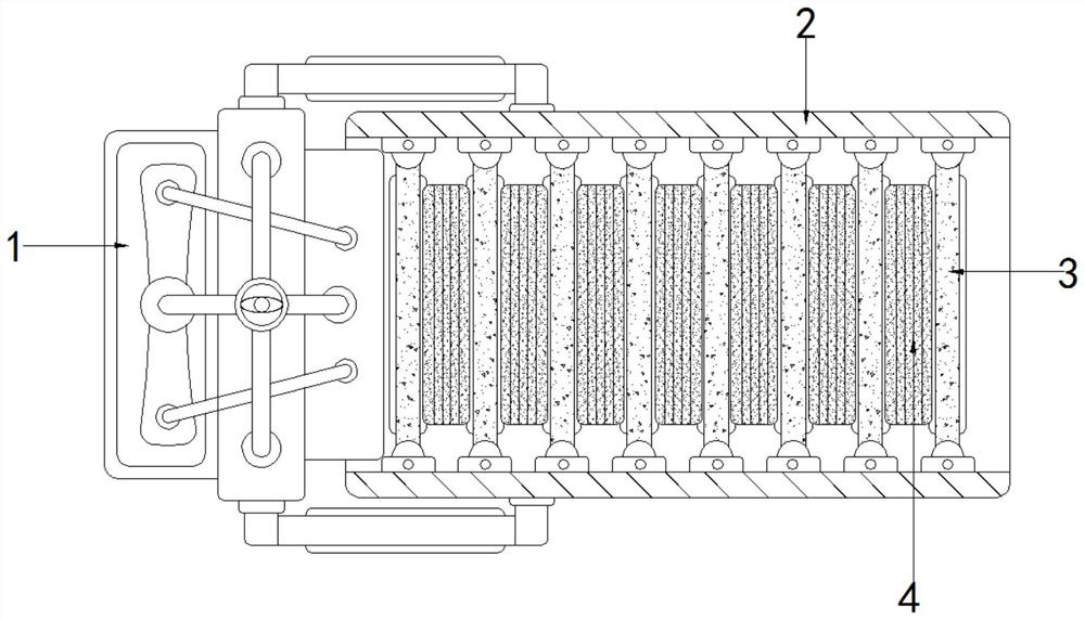
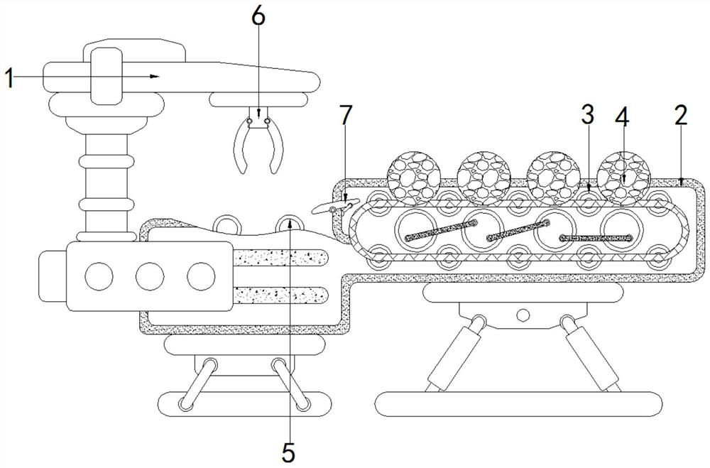
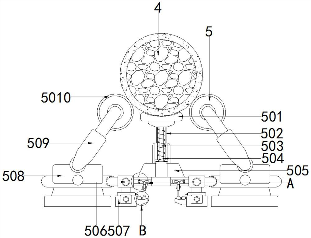
[0022] see Figure 1-6 , a hydraulic clamping stretch forging machine for rod blanks, including a top seat 1, a bracket 2, a roller 3, a processing rod 4, a top piece assembly 5 and a clamping assembly 6, the left side of the top seat 1 and the bracket 2 The right side is fixedly installed, the inner wall of the bracket 2 is movably connected with the outer wall of the roller 3, the outer wall of the roller 3 is movably connected with the outer wall of the proces


PUM


Abstract

The invention relates to the technical field of hydraulic equipment, and discloses a hydraulic clamping and stretching forging machine for a rod blank. The forging machine comprises a top seat, a support, a rolling shaft, a machining rod, an ejector assembly and a clamping assembly, wherein the left side of the top seat and the right side of the support are fixedly installed, the inner wall of the support and the outer wall of the rolling shaft are movably connected, the outer wall of the rolling shaft is movably connected with the outer wall of the machining rod, and the top end of a transition plate is movably connected with the outer wall of the machining rod. According to the hydraulic clamping and stretching forging machine for the rod blank, the rolling shaft rolls to drive the machining rod to move, the machining rod arrives at the right side and moves to the top end of the ejector assembly through the transition plate, a top plate firstly makes contact with the machining rod to be matched with a structure to which the top plate belongs, so that a movable rod moves to achieve closing of a movable switch, an air pump is matched with an air pipe to enable an air pressure rod to ascend to enable the machining rod to ascend, and a guide wheel is matched to enable the machining rod to enter the inner wall of the clamping assembly to achieve clamping, so that in the process of forging machining, feeding and clamping are carried out synchronously.

Description


Claims


Application Information

Patent Timeline
Owner 刘伟伟
Why Eureka
Try Eureka