Computer host drilling equipment and operation method
A kind of drilling equipment and computer technology, applied in drilling/drilling equipment, boring/drilling, metal processing equipment, etc., can solve the problems of low positioning accuracy and low efficiency, and achieve the effect of improving stability
- Summary
- Abstract
- Description
- Claims
- Application Information
AI Technical Summary
Benefits of technology
Problems solved by technology
Method used
Image

Examples
Embodiment 1
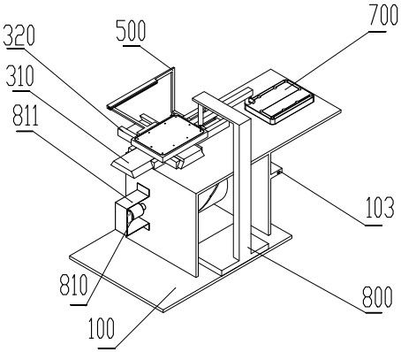
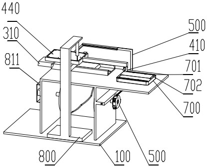
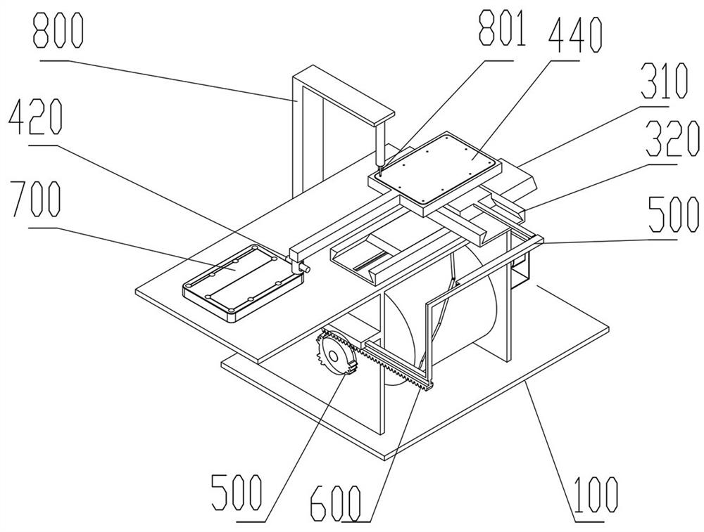
[0031] A computer host drilling equipment, including a workbench 100, a cam 200, a cam slot 202, a No. 1 dovetail slot 301, a No. 1 guide rail 311, a cam lever 312, a No. 2 dovetail slot 321, a No. 2 dovetail guide rail 331, and a mounting plate 400 , sliding sleeve 410, positioning pin 420, cone 421, computer case 440, moving rod 500, incomplete gear 600, first tooth block 602, second tooth block 603, third tooth block 604, positioning plate 700, positioning hole 701 , positioning slot 702, drilling machine 800, motor 810, the top of the workbench 100 has 2 vertical plates 101, and the upper part of the 2 vertical plates 101 has a coaxial cam hole 102, and the outer side of the right vertical plate 101 has a chute 103, the vertical plate The upper part of 101 has a platen 104, the front side of the platen 104 has a platen groove 105, the upper part of the drilling machine 800 has a drill bit 801, the drilling machine 800 is fixedly connected to the rear of the workbench 100, the
Embodiment 2
[0033] The incomplete gear 600 of the present invention has a gear hole 601 in the middle, and the outer side of the gear hole 601 has a first tooth block 602, a second tooth block 603, and a third tooth block 604. The angle between the first tooth block 602 and the second tooth block 603 is about 65.45 degrees, the angle between the third tooth block 604 and the first tooth block 602 is about 163.64 degrees, the first tooth block 602, the second tooth block 603, and the third tooth block 604 mesh with the rack 502 respectively, and the The operation control moving rod 500 moves, and by meshing with the rack 502, the operation control moving rod 500 cooperates with the motor 810 to drive the No. 2 dovetail 330 to move intermittently to complete the positioning and drilling of the computer case 440.
[0034] The gear hole 601 is fixedly connected to the right side of the camshaft 201, the moving rod 500 is in the shape of an "L", the lower part of the moving rod 500 has a slider 50
Embodiment 3
[0040] When the motor 810 rotates, it drives the cam 200 to rotate, and the cam groove 202 rotates with the cam 200. The cam groove 202 drives the cam lever 312 to move left and right, and the cam lever 312 drives the first rail body 310 to move left and right. The second dovetail body 330 moves forward, backward, left, and right in the space, the positioning pin 420 slides up and down inside the sliding sleeve 410, the return spring 430 presses the positioning pin 420 on the lower part of the sliding sleeve 410, and the second dovetail body 330 moves forward, backward, left, and right , to drive the computer casing 440 to move back and forth, left and right, the cone 421 is a cone and has a good positioning effect, under the action of the return spring 430, the cone 421 is positioned in the hole on the upper part of the positioning plate 700 and moves along the groove of the positioning plate 700, After the cone 421 is positioned, the mounting plate 400 will also be positioned, a
PUM
 Abstract
Description
Claims
Application Information
 - R&D Engineer
- R&D Manager
- IP Professional
- Industry Leading Data Capabilities
- Powerful AI technology
- Patent DNA Extraction
Browse by: Latest US Patents, China's latest patents, Technical Efficacy Thesaurus, Application Domain, Technology Topic.
© 2024 PatSnap. All rights reserved.Legal|Privacy policy|Modern Slavery Act Transparency Statement|Sitemap