Efficient cyclone separator adopting liquid washing

A cyclone separator and liquid washing technology, applied in separation methods, dispersed particle separation, chemical instruments and methods, etc., to achieve the effects of simple structure, improved separation efficiency, and ingenious design

Pending Publication Date: 2021-06-29
上海卓旋化工科技有限公司
View PDF2 Cites 0 Cited by
  • Summary
  • Abstract
  • Description
  • Claims
  • Application Information

AI Technical Summary

Benefits of technology

This patented technology describes an improved cyclonic separator used at various stages during oil drilling operations that uses liquids instead of water (liquid). It achieves better performance due to its horizontal arrangement of components such as top and bottom rings on both sides of the separating chamber. Additionally, there is also included fin arrangements within these columns where small liquid droplets pass through while larger solids get trapped more efficiently compared to traditional methods like inclined discs or spirals. Overall, this new design improves the effectiveness and reduction ratio of oil extraction processes without increasing their size.

Problems solved by technology

This patented technical problem addressed by this patents relates to improving the performance of cyclones due to their complicated inner movement caused by multiple components like water droplets and gas bounces during use. Cyclone separators currently exist without optimizing them because they require too much fluid compared to other types of devices.

Method used


Image

  • Efficient cyclone separator adopting liquid washing
  • Efficient cyclone separator adopting liquid washing
  • Efficient cyclone separator adopting liquid washing

Examples


Embodiment Construction

[0039] In order to understand the technical content of the present invention more clearly, the following embodiments are given for detailed description.

[0040] In the description of the present invention, it should be understood that the terms "upper", "lower", "front", "rear", "left", "right", "top", "bottom", "inside", " The orientation or positional relationship indicated by "outside" is based on the orientation or positional relationship shown in the accompanying drawings, and is only for the convenience of describing the present invention and simplifying the description, rather than indicating or implying that the indicated device or element must have a specific orientation, so as to The specific orientation configuration and operation are therefore not to be construed as limitations of the present invention.

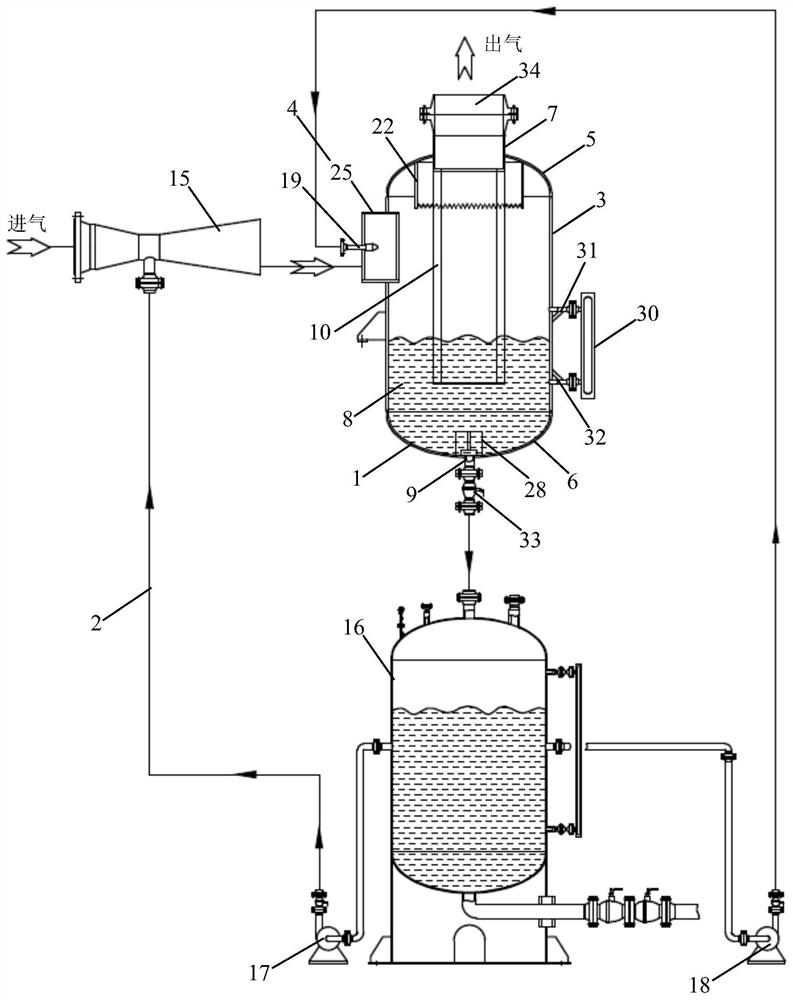
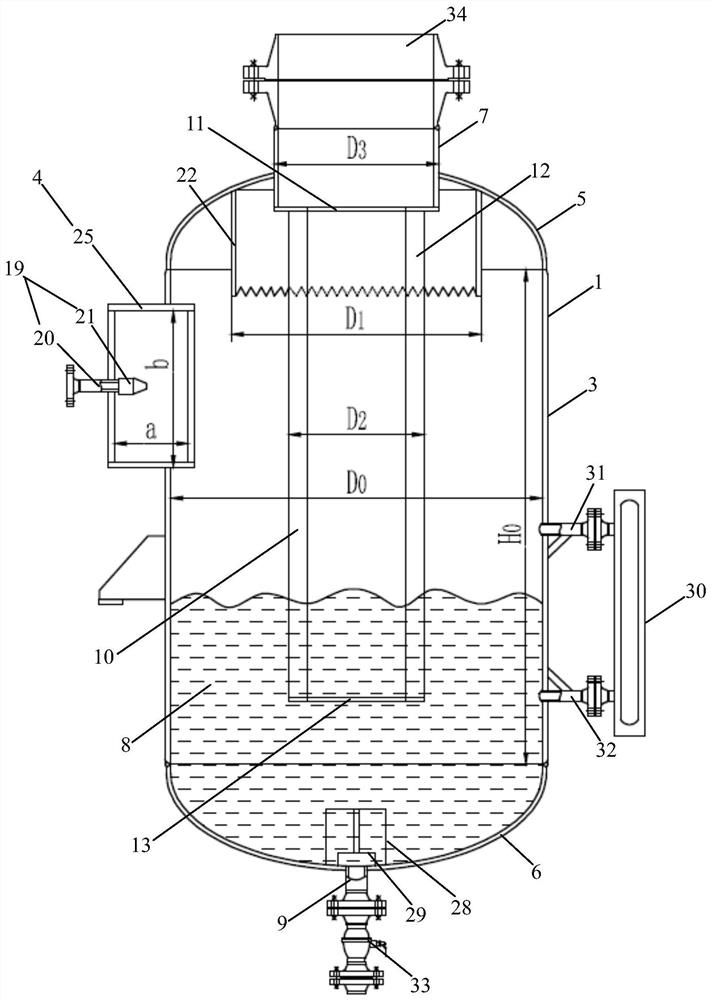
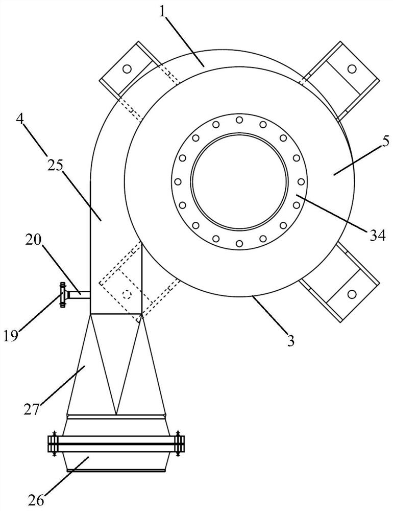
[0041] See Figure 1 to Figure 5 and Figure 8 to Figure 10 As shown, in a specific embodiment of the present invention, the high-efficiency cyclone separator usi


PUM


Abstract

The invention provides an efficient cyclone separator adopting liquid washing. An upper annular plate and a lower annular plate of an interface fluid director of the cyclone separator are both horizontally arranged, an annular fluid director is vertically arranged, the upper annular plate, the annular fluid director and the lower annular plate are all coaxially arranged with a cylinder, the upper annular plate is located in an upper end socket and connected with the lower end of an air outlet pipe, the lower annular plate is located in the lower portion of the cylinder and located in the washing liquid, vertical flow deflectors of the annular fluid director are located between the upper annular plate and the lower annular plate and connected with the upper annular plate and the lower annular plate respectively, the lower ends of the vertical flow deflectors are located in the washing liquid, and the vertical flow deflectors are arranged in the gas rotating direction from inside to outside. Two or more vertical flow deflectors are uniformly distributed along the circumferential direction of the annular fluid director. The cyclone separator can obtain as high cyclone trapping efficiency as possible by using as little liquid as possible, improves the separation efficiency of solid particles of 5 microns or smaller, and is ingenious in design, simple in structure, simple and convenient to manufacture, low in manufacturing cost and suitable for large-scale popularization and application.

Description


Claims


Application Information

Patent Timeline
Owner 上海卓旋化工科技有限公司
Why Eureka
Try Eureka