Grinding device used for removing burrs at cut openings of steel pipes

A steel pipe and cutting technology, applied in the direction of grinding drive device, fixed grinding wheel device, grinding/polishing safety device, etc., can solve the problems of easy deviation of steel pipe, inconvenient grinding of steel pipes of different lengths, etc., and achieve easy disassembly and replacement , the effect of preventing damage

Inactive Publication Date: 2021-09-17
中诚惠容实业集团有限公司
View PDF13 Cites 0 Cited by
  • Summary
  • Abstract
  • Description
  • Claims
  • Application Information

AI Technical Summary

Benefits of technology

This patented technology helps keep small diameter steel tubings (such as drilling tools) stable when they are being worked upon or processed properly without tilting them horizontally due to their movement caused by friction forces. It also allows for precise control over how much pressure needs to be applied while driving it through various sizes of holes made into walls around these tunnels. Additionally, this technology makes it easier to clean up after use because there's no wasted material left behind inside the machine itself.

Problems solved by technology

This patented technology describes an apparatus that can be attached to a conveyor system to remove unwanted material (burs) without interrupting its flow). It includes various parts like a roller mechanism, a controllable member, and other components such as a grip unit, a holding portion, and another part called a control component. These features help improve work efficacy while also making it easier to use these devices over traditional methods.

Method used


Image

  • Grinding device used for removing burrs at cut openings of steel pipes
  • Grinding device used for removing burrs at cut openings of steel pipes
  • Grinding device used for removing burrs at cut openings of steel pipes

Examples


Embodiment Construction

[0024] The technical solutions in the embodiments of the present invention will be clearly and completely described below with reference to the accompanying drawings in the embodiments of the present invention. Obviously, the described embodiments are only a part of the embodiments of the present invention, but not all of the embodiments. Based on the embodiments of the present invention, all other embodiments obtained by those of ordinary skill in the art without creative efforts shall fall within the protection scope of the present invention.

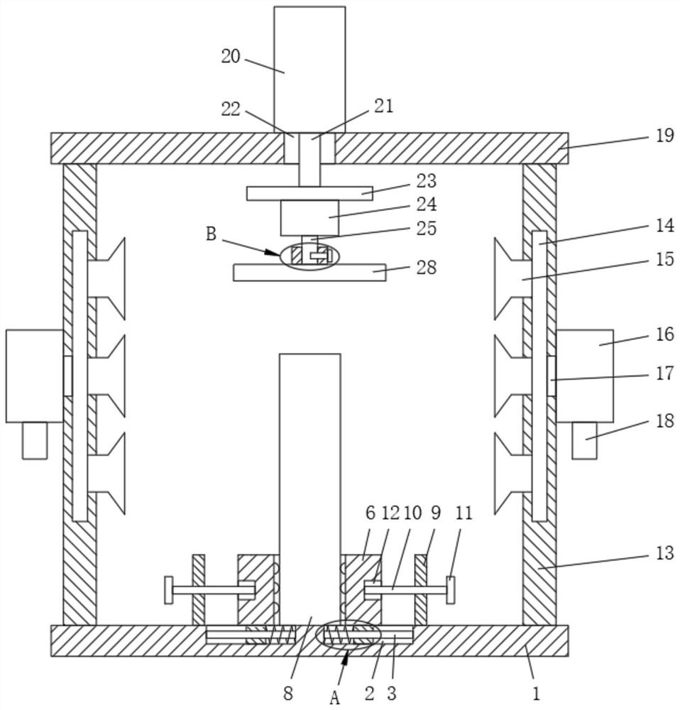
[0025] see figure 1 , figure 2 , image 3 , Figure 4 , Figure 5 , a grinding device for removing burrs of steel pipe cuts, comprising a base plate 1, a guide groove 2 is provided on the base plate 1, a guide rod 3 is provided inside the guide groove 2, a spring 4 is provided on the outside of the guide rod 3, and the guide rod 3 A guide block 5 is slidably connected to the outer side of the guide block 5, and the guide block 5 is


PUM


Abstract

The invention discloses a grinding device used for removing burrs at cut openings of steel pipes. The grinding device comprises a bottom plate, guide grooves are formed in the bottom plate, guide rods are arranged in the guide grooves, springs are arranged on the outer sides of the guide rods, the outer sides of the guide rods are slidably connected with guide blocks in a sleeved manner, the guide blocks are slidably connected with the guide grooves, clamping sleeves are fixedly connected to the guide blocks, the clamping sleeves are fixedly connected with protruding blocks, the protruding blocks are in contact with a steel pipe, the steel pipe is in contact with the bottom plate, and the bottom plate is fixedly connected with a fixed seat. By designing the clamping sleeves, the protruding blocks and the steel pipe to be in contact, a clamping and positioning effect can be achieved on the steel pipe, the steel pipe can be prevented from moving in the horizontal direction, and therefore the situation that the steel pipe deviates to affect the grinding effect during grinding is avoided, the distance between the two clamping sleeves can be adjusted, and therefore the device can grind steel pipes with different diameters.

Description


Claims


Application Information

Patent Timeline
Owner 中诚惠容实业集团有限公司
Why Eureka
Try Eureka