Environment-friendly gasoline engine particle trap

A particle trap and environmental protection technology, applied in the direction of machines/engines, mechanical equipment, engine components, etc., can solve problems such as inconvenient operation, regeneration delay or increase of regeneration temperature, and lower installation efficiency, so as to achieve convenient positioning and connection , reasonable structure, and the effect of improving installation efficiency

Active Publication Date: 2021-09-24
宁波开特环保科技有限公司
View PDF7 Cites 0 Cited by
  • Summary
  • Abstract
  • Description
  • Claims
  • Application Information

AI Technical Summary

Benefits of technology

This patented device allows for efficient capturing machines with an improved mounting process due to its ability to move the exhaust system smoothly along different directions during operation without interference from other components or external forces such as vibrations caused by vehicle motion.

Problems solved by technology

Increasing environmental concerns have led researchers towards developing new methods for reducing harmful substances released during combustion processes such as automobile manufacture. One approach involves adding materials like aluminum powder to filters called particulates, allowing these metals to break down when they hit metal surfaces causing damage. However, current techniques require frequent replacement due to accumulation of ash debris over time. Another solution includes attaching weights made of plastic resin to the devices themselves, making their removal difficult without damaging surrounding equipment.

Method used


Image

  • Environment-friendly gasoline engine particle trap
  • Environment-friendly gasoline engine particle trap
  • Environment-friendly gasoline engine particle trap

Examples


Embodiment Construction

[0026] Describe the present invention in further detail below in conjunction with accompanying drawing:

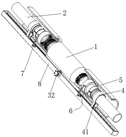
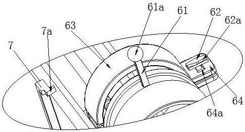
[0027] Such as Figure 1 to Figure 5 As shown, an environmental protection type gasoline engine particulate trap includes a trap 1 and an exhaust pipe 2 connected to both ends of the trap 1, and the exhaust pipe 2 is respectively fixed on a limit movement mechanism, The limit movement mechanism is driven by a two-way drive mechanism to move synchronously. The two-way drive mechanism includes a screw rod 31 and a driving member that drives the screw rod to rotate. 31a, the position-limiting movement mechanism includes a rotationally fitted clamping mechanism 6 and a position-limiting member 4, the exhaust pipe 2 is placed on the corresponding clamping mechanism 6, and the position-limiting member 4 is provided with The slider 41 matched with the corresponding threaded segment 31a; the limit movement mechanism is placed in the corresponding conduit 5, and the guide groove 5 is


PUM


Abstract

The invention discloses an environment-friendly gasoline engine particle trap. The environment-friendly gasoline engine particle trap comprises a trap body and exhaust pipes connected to the two ends of the trap body, the exhaust pipes are fixed to limiting moving mechanisms, the limiting moving mechanisms are driven by a bidirectional driving mechanism to move synchronously, the bidirectional driving mechanism comprises a screw rod and a driving part driving the screw to rotate, threaded sections with opposite rotating directions are arranged at the two ends of the screw rod, each limiting moving mechanism comprises a clamping mechanism and a limiting piece which are rotationally matched, and sliding blocks matched with the corresponding threaded sections are arranged on the limiting pieces; and the limiting moving mechanisms are arranged in corresponding guide pipes, guide grooves are formed in the guide pipes, each guide groove comprises a linear section and a spiral section which are connected, guide rods matched with the guide grooves are arranged on the clamping mechanisms, lock catches are arranged on the clamping mechanisms, unlocking pieces used for releasing the clamping mechanisms from clamping the exhaust pipes after the exhaust pipes are connected with the trap body are fixed beside the screw rod, and the unlocking pieces are matched with the lock catches. The trap has the advantages of being reasonable in structure, convenient to position and install and capable of improving installation efficiency.

Description


Claims


Application Information

Patent Timeline
Owner 宁波开特环保科技有限公司
Why Eureka
Try Eureka