Combined land preparation machine

A soil leveling machine and soil leveling technology, which is applied to agricultural machinery and implements, shovels, plows, etc., can solve the problems of inconvenient adjustment of the angle of the rake blades, and achieve the effects of stable and convenient adjustment, good soil leveling effect and compact structure.

Inactive Publication Date: 2021-11-05
宜兴博登泰科工业装备有限公司
View PDF1 Cites 2 Cited by
  • Summary
  • Abstract
  • Description
  • Claims
  • Application Information

AI Technical Summary

Benefits of technology

This patented technology allows for easy movement between different parts within an agricultural machine without causing damage or affects its performance. It achieves this through various technical features like stabilizing tension angles, reducing slip movements, connecting multiple components together smoothly, maintaining proper distance from each other while excavations, prevention of ghostings caused by uneven surfaces, protection against impact loads, automatic vibration control, compensated workspace design, and improved maneuverability when moving over obstacles.

Problems solved by technology

This patented describes an apparatus called Harrow (H) that helps prepare dirt from fields without requiring heavy equipment or excessive energy usage compared to traditional methods like shovelling. However, this technology has limitations such as limited working range due to its fixed position relative to ground surface, difficulty in turning over uneven surfaces, and increased weight loadings during use. To address these issues, there have been developed various techniques including combining multiple machines together to make better results while reducing their own workload.

Method used


Image

  • Combined land preparation machine
  • Combined land preparation machine
  • Combined land preparation machine

Examples


Embodiment 1

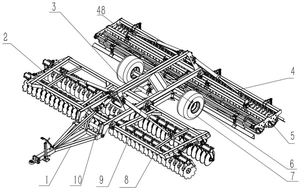
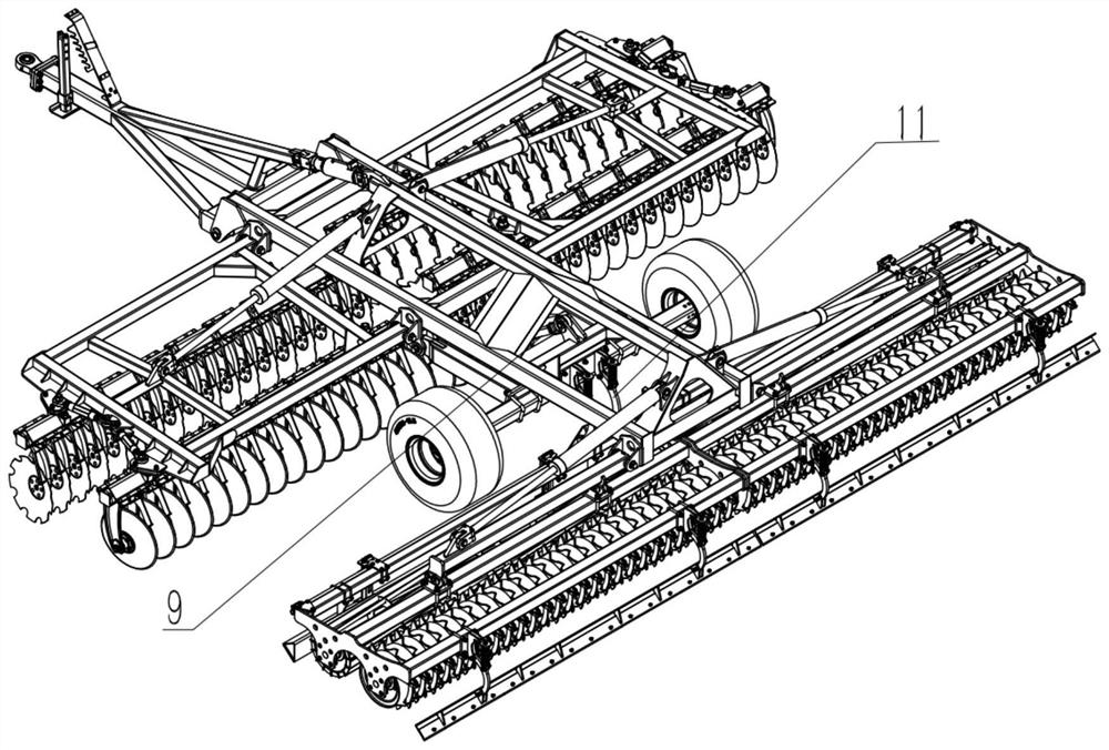
[0042] refer to Figure 1~Figure 3 , a combined land preparation machine, including a main rake frame 3, a rake group, a packer leveling device, a traction frame 1 and a traveling wheel 7; the rake group includes a left rake group 8 and a right rake group 2, and the packer is flat The soil device includes a left packer leveling assembly 5 and a right packer leveling assembly 48, the rake angles on the left rake group 8 and the right rake group 2 can be adjusted, and the left rake group 8 and the right rake group 2 is connected to the left and right sides of the main rake frame 3 in a foldable manner; Side; the front end of the main rake frame 3 is provided with a traction frame 1, and the rake group is located in front of the packer leveling device; the walking wheel shaft 6 is connected to the main rake frame 3 in a stowable manner. In the transportation state, the road wheels 7 are on the ground, and in the working state, the road wheels 7 are off the ground to ensure the oper

Embodiment 2

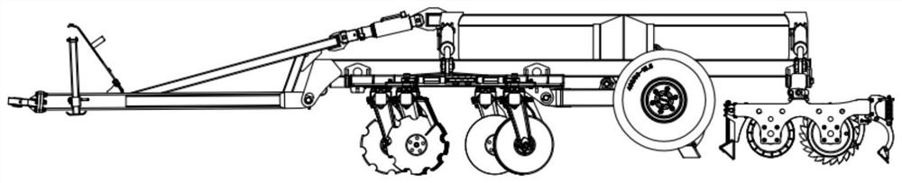
[0060] On the basis of Embodiment 1, the rear end of the traction frame 1 is flexibly connected to the main rake frame 3, and the front end of the traction frame 1 is connected to the main rake frame 3 through an oil cylinder with an adjustable stroke. When the tractor is pulling behind, adjust the best pulling point position of the main rake frame.

Embodiment 3

[0062] On the basis of Embodiment 1, the left rake group and the right rake group are connected to the left and right sides of the main rake frame 3 through folding oil cylinders, and the left packer leveling assembly and the right packer leveling assembly It is connected to the left and right sides of the main rake frame 3 through a folding oil cylinder, and the folding oil cylinder is connected with an overload protection hydraulic system, and the overload protection hydraulic system includes an accumulator. When the soil component encounters steep slopes, mounds of soil, or encounters bumps during transportation, the oil cylinder shrinks instantly and the pressure is too large, and the accumulator will prevent the oil cylinder from overloading and increase the service life of the oil cylinder. At the same time, the profiling effect can be achieved in the cultivation process, which can make the cultivation coverage wider and reduce the missing tillage rate of the cultivation lan


PUM


Abstract

The invention discloses a combined land preparation machine which comprises a main harrow frame, harrow sets, a compacting machine soil leveling device and walking wheels, the angles of harrow pieces on the harrow sets are adjustable, the harrow sets comprise the left harrow set and the right harrow set, the compacting machine soil leveling device comprises a left compacting machine soil leveling assembly and a right compacting machine soil leveling assembly, the left harrow set and the right harrow set are connected to the left side and the right side of the main harrow frame in a foldable mode, the left compacting machine soil leveling assembly and the right compacting machine soil leveling assembly are connected to the left side and the right side of the main harrow frame in a foldable mode, the compacting machine soil leveling device is located at the rear ends of the harrow sets, and a traction frame is arranged at the front end of the main harrow frame, so that harrow blades are more convenient to adjust.

Description


Claims


Application Information

Patent Timeline
Owner 宜兴博登泰科工业装备有限公司
Why Eureka
Try Eureka