Natural gas pressure energy utilization system

A technology of pressure energy and natural gas, applied in pipeline systems, gas/liquid distribution and storage, steam engine installations, etc., can solve the problems of unsuitable natural gas pressure energy, inconvenience to reuse natural gas, mixed with air bubbles, etc., and achieve high power generation efficiency and structure. Simple, low-cost effects

Pending Publication Date: 2021-12-17
四川道唯乐科技有限责任公司
View PDF3 Cites 0 Cited by
  • Summary
  • Abstract
  • Description
  • Claims
  • Application Information

AI Technical Summary

Problems solved by technology

When the device is used for natural gas wellhead pressure energy utilization, due to the contact between gas and liquid, when high-pressure natural gas is passed into the pressure-resistant water storage device, the gas will impact the liquid, the liquid will be atomized and foamed, and the atomized l

Method used


Image

  • Natural gas pressure energy utilization system
  • Natural gas pressure energy utilization system
  • Natural gas pressure energy utilization system

Examples


Embodiment Construction

[0025] The present invention will be further described below in conjunction with the accompanying drawings and embodiments.

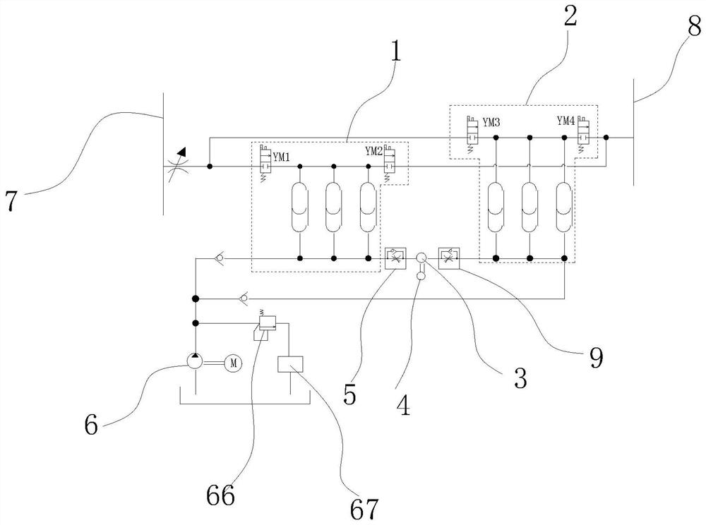
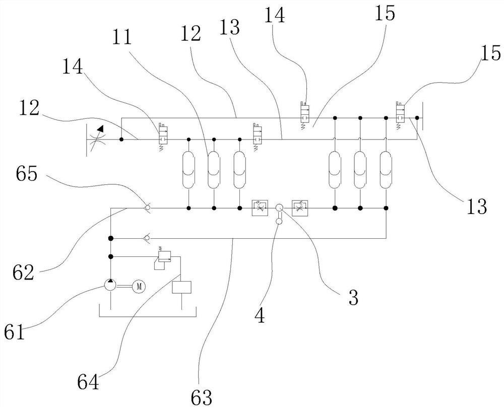
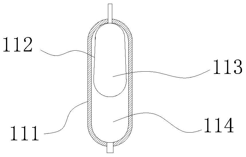
[0026] Such as Figure 1 to Figure 3 As shown, the natural gas pressure energy utilization system of the present invention includes a first pressure energy conversion unit 1 , a second pressure energy conversion unit 2 , a hydraulic transmission device 3 and a generator 4 . The first pressure energy conversion unit 1 and the second pressure energy conversion unit 2 respectively include pressure conversion components. The pressure conversion assembly includes an intake pipe 12 , an exhaust pipe 13 and at least one energy conversion device 11 . The energy conversion device 11 includes a casing 111 and a movable sealing structure 112, the movable sealing structure 112 is movably arranged in the casing 111, and divides the inner chamber of the casing 111 into a first medium chamber 114 and a second medium chamber 114. The medium chamber 113 can adjust the si


PUM


Abstract

The invention provides a natural gas pressure energy utilization system which is low in equipment manufacturing cost, high in energy conversion efficiency and suitable for natural gas pressure energy utilization, and relates to the technical field of pressure energy utilization. The natural gas pressure energy utilization system comprises a first pressure energy conversion unit, a second pressure energy conversion unit, a hydraulic transmission device and a power generator, wherein the first pressure energy conversion unit and the second pressure energy conversion unit each comprise a pressure conversion assembly; the pressure conversion assembly comprises an air inlet tube, an exhaust tube and at least one energy conversion device; the energy conversion device comprises a shell and a movable sealing structure, the movable sealing structure divides an inner cavity of the shell into a first medium cavity and a second medium cavity, an air inlet control valve is arranged on the air inlet tube, an exhaust control valve is arranged on the exhaust tube, and one end of the air inlet tube and one end of the exhaust tube are both communicated with the second medium cavity. The system is simple in structure, low in manufacturing cost, convenient to maintain and high in power generation benefit.

Description


Claims


Application Information

Patent Timeline
Owner 四川道唯乐科技有限责任公司
Why Eureka
Try Eureka