Folding capacitive load electrode structure, electro-optical modulator and preparation method of electro-optical modulator
An electro-optic modulator and capacitive load technology, which is applied in the field of optical communication technology and integrated optical modulation, can solve the problems of large microwave loss and low performance of electro-optic modulators, and achieve the effects of minimizing parasitic capacitance, improving performance, and suppressing excitation
- Summary
- Abstract
- Description
- Claims
- Application Information
AI Technical Summary
Problems solved by technology
Method used
Image

Examples
Embodiment 1
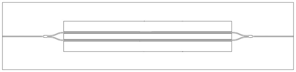
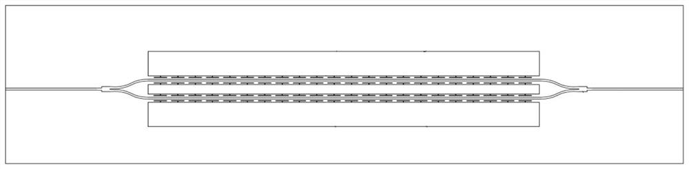
[0044] see Figure 3-Figure 4 , this embodiment proposes a folded capacitive load electrode structure, including a main signal electrode 21, a first main ground electrode 22, and a second main ground electrode 23, wherein the first main ground electrode 22-main signal electrode 21-second The main ground electrode 23 forms the G-S-G coplanar waveguide transmission line 2, including a straight transmission line part and a curved transmission line part; in the straight transmission line part, both sides of the main signal electrode 21 are connected to load T-type electrodes, the first main ground electrode 22 and the second main ground One side between the electrode 23 and the main signal electrode 21 is connected to a loaded T-shaped electrode; the part of the transmission line is bent, and the main signal electrode 21 erects several air bridges at the bend to connect the first main ground electrode 22 and the second main ground electrode 23 ;
[0045] In this embodiment, the m...
Embodiment 2
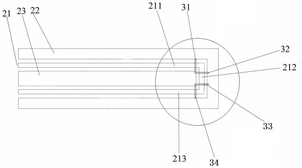
[0049] see Figure 5-Figure 6 , this embodiment proposes a folded capacitive load electrode structure, and chamfers are provided on the outside of the corner structure.
[0050] In this embodiment, the main signal electrode 21 includes a first straight main signal electrode 211, a first curved main signal electrode 212, a second straight main signal electrode 213, a first electrode chamfer 2121 and a second electrode chamfer 2122; One end of the first electrode chamfer 2121 is connected to the first straight main signal electrode 211, and the other end is connected to the first curved main signal electrode 212;
[0051] One end of the second electrode chamfer 2122 is connected to the first curved main signal electrode 212 , and the other end is connected to the second straight main signal electrode 213 .
[0052] In this embodiment, there are four air bridges, which are set up respectively above the first electrode chamfer 2121 and the second electrode chamfer 2122, and the a...
Embodiment 3
[0056] see Figure 5-Figure 6 , this embodiment proposes a folded capacitive load electro-optic modulator, the modulator is a two-stage folded capacitive load electro-optic modulator that is folded once, including when n=1 proposed in Embodiment 1, A folded capacitive load electrode structure and a lithium niobate waveguide structure folded once, the lithium niobate waveguide structure is arranged on the folded capacitive load electrode structure; the lithium niobate waveguide structure includes a first waveguide 111 and The second waveguide 112; the first waveguide 111 is installed between the loading T-shaped electrodes 4 respectively arranged on the first main ground electrode 22 and the first direct main signal electrode 211, and respectively arranged on the second main ground electrode 23 and the loading T-type electrode 4 on the second straight main signal electrode 212; the second waveguide 112 is installed on the loading T-type electrode 4 respectively arranged on the ...
PUM
 Abstract
Description
Claims
Application Information
 - R&D Engineer
- R&D Manager
- IP Professional
- Industry Leading Data Capabilities
- Powerful AI technology
- Patent DNA Extraction
Browse by: Latest US Patents, China's latest patents, Technical Efficacy Thesaurus, Application Domain, Technology Topic.
© 2024 PatSnap. All rights reserved.Legal|Privacy policy|Modern Slavery Act Transparency Statement|Sitemap