Automatic power generation device for underwater unmanned vehicle

An unmanned aerial vehicle and automatic power generation technology, applied in electromechanical devices, electrical components, electric components, etc., can solve the problems of weakened concealment and safety, increased cost, low power generation, etc., to extend the voyage cycle and working time , simple structure, simple control effect

Active Publication Date: 2022-02-15
HARBIN ENG UNIV
View PDF12 Cites 0 Cited by
  • Summary
  • Abstract
  • Description
  • Claims
  • Application Information

AI Technical Summary

Benefits of technology

This patented technology uses tiny balls called spheroids made up from multiple wires wrapped together inside a cylinder or tube with open ends for generating electrical current by making them move backward and forward repeatedly during their motion. These movements are used to create powerful force on other parts like batteries while also allowing these vehicles to continue moving through water even if they have been lost due to damage caused by waves hitting against obstacles such as rocks or dunes.

Problems solved by technology

The technical problem addressed in this patents relating to undersea robots lies in their lack of durable electrical sources like Liquids while being able to efficiently operate over longer periods of time. Existing solutions require bulky structures made up entirely of heavy metals, leading to increased risk of corrosion damage during deployment operations. There is currently a demand for smaller ballastless drones capable of autonomous operation within 360 degrees of freedom.

Method used


Image

  • Automatic power generation device for underwater unmanned vehicle
  • Automatic power generation device for underwater unmanned vehicle
  • Automatic power generation device for underwater unmanned vehicle

Examples


Embodiment Construction

[0028] The following will clearly and completely describe the technical solutions in the embodiments of the present invention with reference to the accompanying drawings in the embodiments of the present invention. Obviously, the described embodiments are only some, not all, embodiments of the present invention. Based on the embodiments of the present invention, all other embodiments obtained by persons of ordinary skill in the art without making creative efforts belong to the protection scope of the present invention.

[0029] In order to make the above objects, features and advantages of the present invention more comprehensible, the present invention will be further described in detail below in conjunction with the accompanying drawings and specific embodiments.

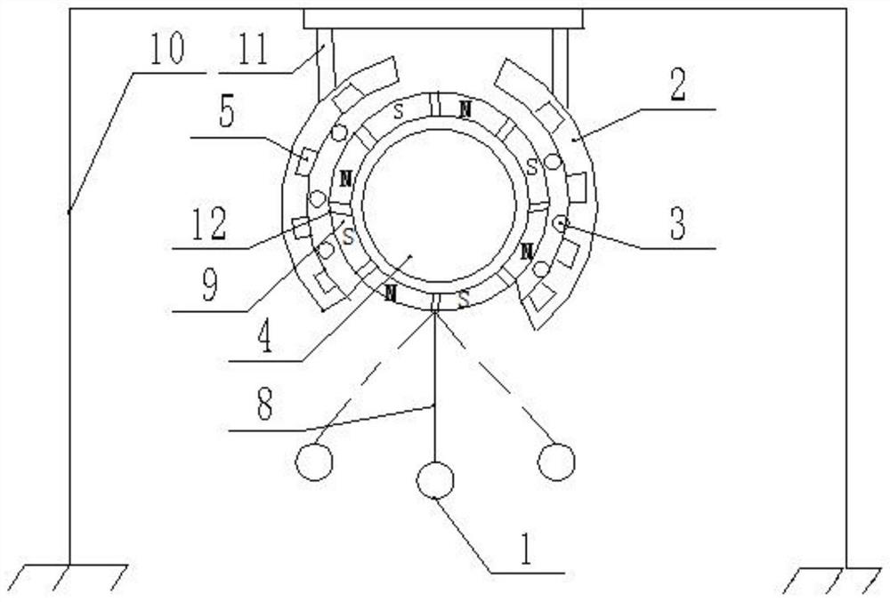
[0030] The invention provides an automatic power generation device for an underwater unmanned vehicle, which includes a bracket, a rectifier, a power generation cabin and a movable ball 1;

[0031] The power generati


PUM


Abstract

The invention discloses an automatic power generation device for an underwater unmanned vehicle, which is used for the underwater unmanned vehicle. The device comprises a bracket, a power generation cabin and a movable ball; the power generation cabin comprises stator petals, balls and rotor balls; the stator petals are fixedly connected with the bracket; the number of the stator petals is four. A set of alternating current winding is arranged in each stator petal; the four alternating-current windings are connected in series/in parallel; a plurality of permanent magnets with staggered N poles and S poles are attached to the outer surface of the rotor ball; the balls are arranged between the inner sides of the stator petals and the permanent magnets; the rotor balls are connected with the movable ball through a connecting rope; a electromagnetic winding is electrically connected with a rectifier, and the rectifier is electrically connected with a storage battery of the unmanned underwater vehicle. The movable ball drags the rotor balls to enable the power generation cabin to generate power, alternating current in the alternating current windings in the four stator petals is rectified by the rectifier and then charges the storage battery, and the navigation period and the working time of the unmanned underwater vehicle are prolonged.

Description


Claims


Application Information

Patent Timeline
Owner HARBIN ENG UNIV
Why Eureka
Try Eureka