Toughening equipment for polyester resin

A polyester resin and toughening technology, applied in the field of polyester resin, can solve the problems of unfavorable dispersion of the second phase material, affecting the toughening effect of polyester resin, difficult to rotate and mix, etc., to achieve toughening effect, facilitate dispersion, The effect of internal fluid uniformity

Inactive Publication Date: 2022-04-15
安徽永昌新材料有限公司
View PDF0 Cites 0 Cited by
  • Summary
  • Abstract
  • Description
  • Claims
  • Application Information

AI Technical Summary

Benefits of technology

This patented technology allows for efficient use of polymer materials during manufacturing processes such as injection moldings or casting operations. By utilizing multiple motors driven threads, rods, posts, platforms, guiding plugs, adjustment plates, etc., these movements cause the materials to be mixed smoothly without any problems like they clump due to gravity. Additionally, it simplifies the process of adding different types of chemical agents into the mixture while maintaining its desired properties. Overall, this technology improves product quality control over production lines.

Problems solved by technology

The technical problem addressed by this patented method relates to developing a new type of device that allows for better mixing between two phases during use without compromising their strength and durability when exposed to high temperatures and stresses while also being able to improve the impact resistant and tarnish resistance performance of these modified epoxy compositions (ECOC).

Method used


Image

  • Toughening equipment for polyester resin
  • Toughening equipment for polyester resin
  • Toughening equipment for polyester resin

Examples


Embodiment Construction

[0024] The following will clearly and completely describe the technical solutions in the embodiments of the present invention with reference to the accompanying drawings in the embodiments of the present invention. Obviously, the described embodiments are only some, not all, embodiments of the present invention.

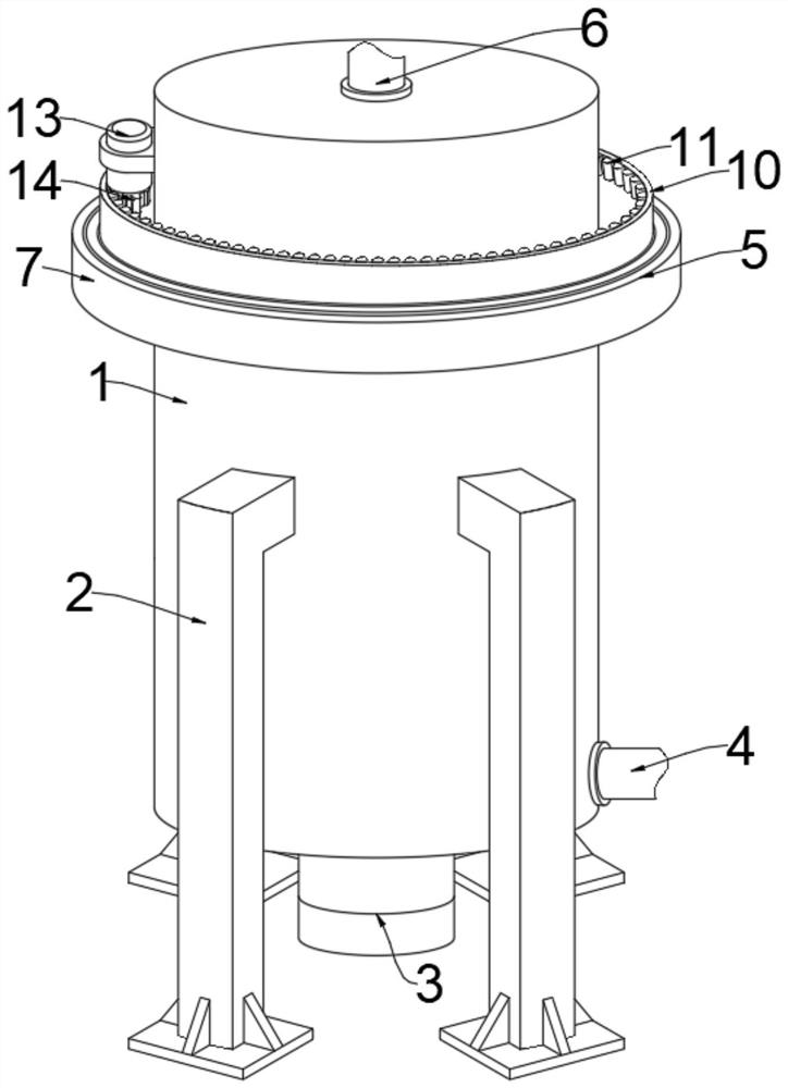
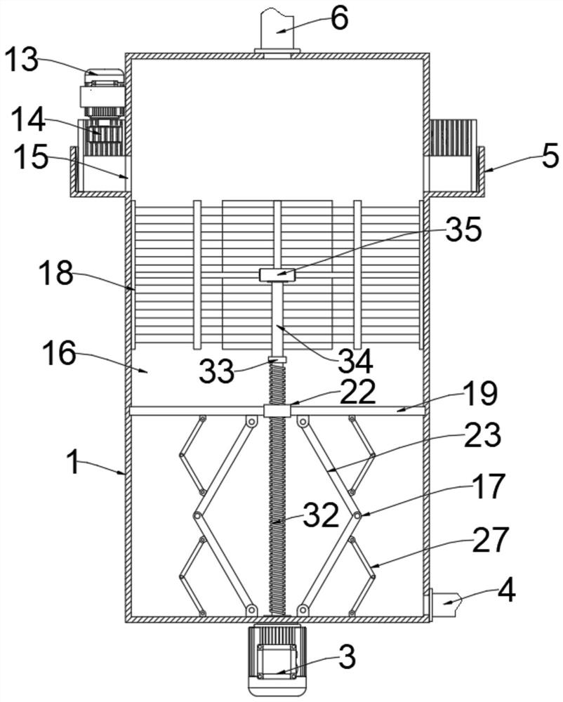
[0025] see Figure 1-5, an embodiment provided by the present invention: a kind of toughening equipment for polyester resin, including a protective shell 1, the cross direction of the outer side of the protective shell 1 is welded with supporting legs 2, and the middle of the upper end of the protective shell 1 is installed with a Liquid pipe 6, the lower end of the outer side of the protective shell 1 is equipped with a liquid discharge pipe 4, the middle of the lower end of the protective shell 1 is installed with a first drive motor 3, the inside of the protective shell 1 is provided with a mixing chamber 16, a liquid inlet pipe 6 and a liquid discharge pipe 4 commun


PUM


Abstract

The invention discloses toughening equipment for polyester resin, relates to the related field of polyester resin, and aims to solve the problems that a current polyester resin material is relatively difficult to rotate and mix in a fluid state, an added second-phase material is not beneficial to being dispersed in the polyester resin material, and the toughening effect of the polyester resin is influenced. A first driving motor is installed in the middle of the lower end of the protective shell, a mixing cavity is formed in the protective shell, a driving threaded rod is arranged at the lower end of the interior of the mixing cavity along the output shaft end of the first driving motor, and an up-down mixing unit is arranged at the lower end of the interior of the mixing cavity along the outer side of the driving threaded rod; the up-down mixing unit comprises a moving disc, a threaded column is arranged in the middle of the moving disc, the threaded column is in threaded connection with the driving threaded rod, the up-down mixing unit comprises a first mixing assembly, and the first mixing assembly comprises a first adjusting plate and a second adjusting plate.

Description


Claims


Application Information

Patent Timeline
Owner 安徽永昌新材料有限公司
Why Eureka
Try Eureka