Machine tool management device for numerical control machine tool

A tool management and CNC machine tool technology, which is applied in the direction of manufacturing tools, metal processing machinery parts, metal processing equipment, etc., can solve the problems of laborious picking and placing operations, low intelligence, and more than one tool, and achieve labor-saving picking and placing operations. High degree of intelligence, easy to adjust the effect of lifting

Inactive Publication Date: 2022-05-13
江苏晟方斯机械科技有限公司
View PDF1 Cites 0 Cited by
  • Summary
  • Abstract
  • Description
  • Claims
  • Application Information

AI Technical Summary

Benefits of technology

The present in this patented technology allows tools stored within different types of carriers (such as carts) to have their own unique features such as being able to switch from one type of carrier to another without having to move them around or even remove any items they are carrying. This makes handling these objects easier than ever before because there're no extra steps needed after placing new ones on top. Additionally, when an item needs replacing, users don’t require complicated procedures like removing old equipment first. Overall, this innovation improves efficiency and ease of use over traditional methods used at machining centres.

Problems solved by technology

This patented describes an improved system called Cnc Machine Tool Management (CMTM) System for storing and accessing cutting tools without requiring physical handling. One problem addressed in this patents relating to improving efficiency when managing these tools involves finding ways to temporarily hold their positions while they may still require manipulation after being removed from the main body.

Method used


Image

  • Machine tool management device for numerical control machine tool
  • Machine tool management device for numerical control machine tool
  • Machine tool management device for numerical control machine tool

Examples


Embodiment

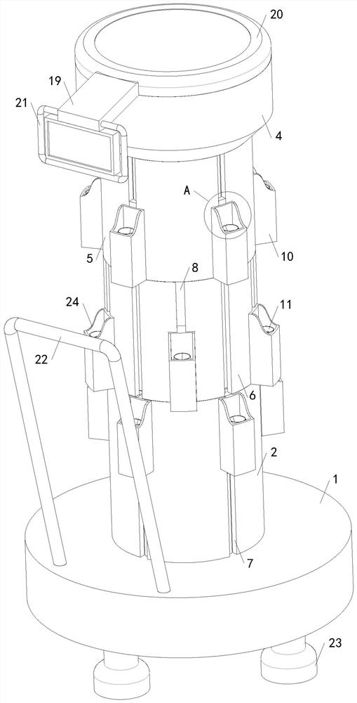
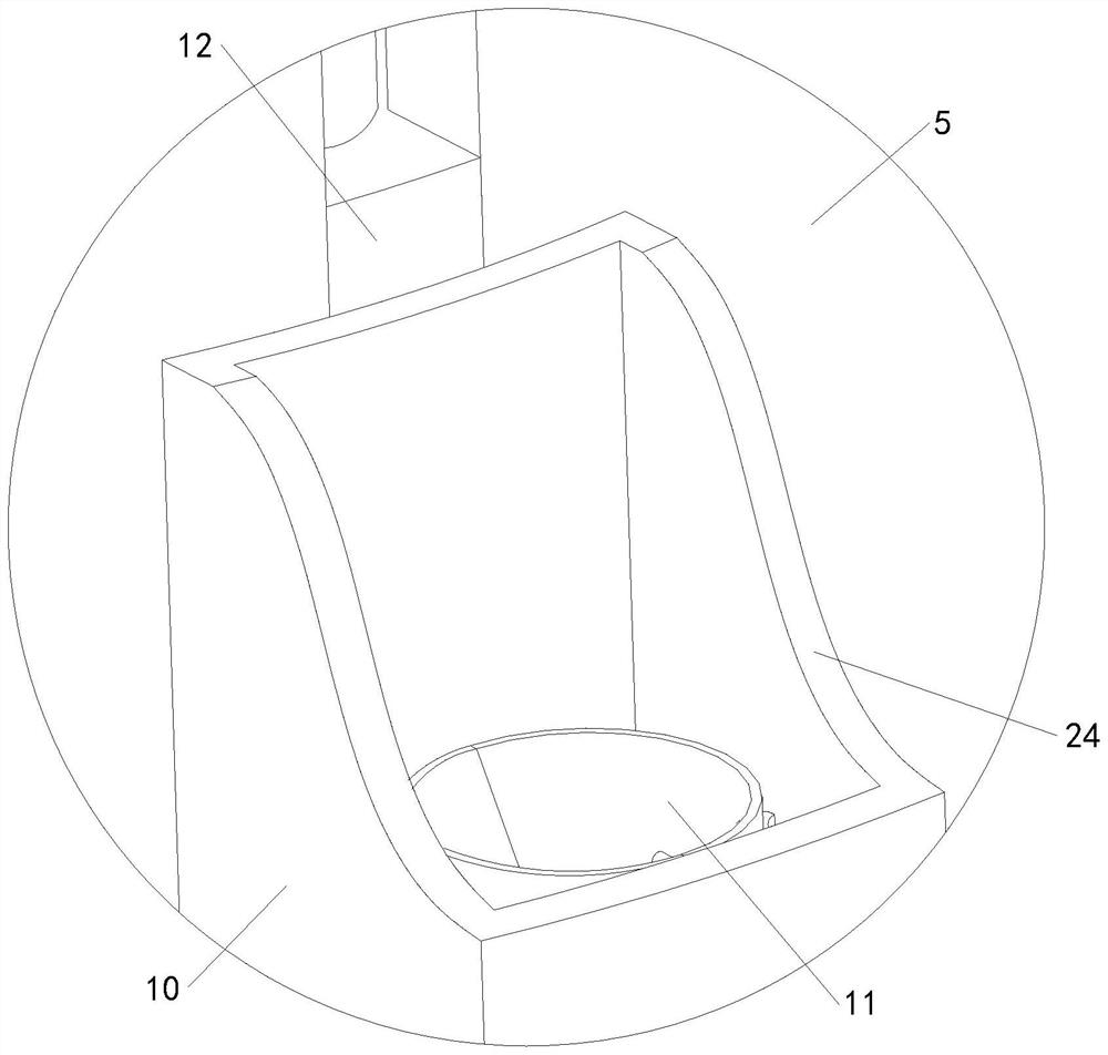
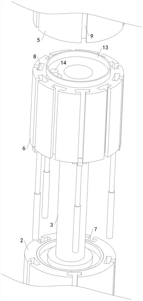
[0029] see Figure 1-6 , a machine tool management device for a CNC machine tool, comprising a base 1, a base connecting frame 2 and a stem 3, a push handle 22 is installed on the top of the base 1, a leg 23 is installed on the bottom of the base 1, and the inside of the leg 23 is Universal wheels with electric drive lifting function are installed, the base connecting frame 2 and the stem 3 are fixedly connected to the top of the base 1, and the top of the stem 3 extends through the base connecting frame 2 to the top of the base connecting frame 2 , the top of the stem 3 is fixedly connected with a top mounting frame 4, the bottom of the top mounting frame 4 is rotatably connected with a secondary connecting frame 5, the bottom end of the secondary connecting frame 5 is rotatably connected with a primary connecting frame 6, and the primary connecting frame 6 is rotationally connected with the basic connecting frame 2, and a servo drive system is provided between the primary conne


PUM


Abstract

The invention relates to the technical field of machine tool cutter management devices, and provides a machine tool cutter management device for a numerical control machine tool, which has the advantages that the heights of a plurality of upper and lower cutter boxes can be mutually switched, the cutter taking and placing operation is labor-saving, the cutter placing process is safe, the intelligent degree is high, the cutter taking and using are convenient, and the practicability is high. Comprising a base, a basic connecting frame and a core column, the basic connecting frame and the core column are both connected with the base, the core column is connected with a top mounting frame, the top mounting frame is connected with a first-stage connecting frame through a second-stage connecting frame, and servo driving systems are arranged between the first-stage connecting frame and the basic connecting frame and between the first-stage connecting frame and the second-stage connecting frame; a plurality of basic lifting grooves are formed in the basic connecting frame, a plurality of first-stage lifting grooves are formed in the first-stage connecting frame, a plurality of second-stage lifting grooves are formed in the second-stage connecting frame, cutter boxes are arranged in the basic lifting grooves, the first-stage lifting grooves and the second-stage lifting grooves, and two half horns are installed in each cutter box.

Description


Claims


Application Information

Patent Timeline
Owner 江苏晟方斯机械科技有限公司
Why Eureka
Try Eureka