Hot flue gas treatment device and treatment method for industrial furnace

A technology of a processing device and an industrial furnace, applied in the field of industrial furnaces, can solve the problems of inconvenient heating, slow purification, easy clogging of the filter, etc., and achieve the effects of speeding up purification, easy installation and disassembly, and speeding up the speed.

Pending Publication Date: 2022-05-27
陕西备晟科技有限公司
View PDF0 Cites 0 Cited by
  • Summary
  • Abstract
  • Description
  • Claims
  • Application Information

AI Technical Summary

Benefits of technology

This patented technology relates to improving the efficiency and effectiveness of removing impurities (such as ash) found on filters used in industry equipment such as boilers. It involves adding a special type of cleaner called antifriction rods onto certain parts of the machine's filtering system. These tools help clear debris without blocking them while also allowing quicker replacement of these filters. Additionally, there may have other mechanisms like a limited connection between the machines themselves, making maintenance easier. Overall, this innovation enhances the performance and durability of the filtrations systems by providing better control over their operation.

Problems solved by technology

Technological Problem addressed in this patents relates to improving the performance and functionality of conventional methods for treating exhaust gases produced through industrial processes involving burning fuels like coal or charcoal. These current techniques have drawbacks including difficulty attaching filters due to blockages caused by particles in the airflow, difficulties installing and removing purifying assemblies, issues associated with accumulation of condensation water after cool down, energy wastage, poor control over temperature levels within the system, etcetera.

Method used


Image

  • Hot flue gas treatment device and treatment method for industrial furnace
  • Hot flue gas treatment device and treatment method for industrial furnace
  • Hot flue gas treatment device and treatment method for industrial furnace

Examples


Embodiment Construction

[0052] The technical solutions in the embodiments of the present invention will be clearly and completely described below with reference to the accompanying drawings in the embodiments of the present invention. Obviously, the described embodiments are only a part of the embodiments of the present invention, but not all of the embodiments. Based on the embodiments of the present invention, all other embodiments obtained by those of ordinary skill in the art without creative efforts shall fall within the protection scope of the present invention.

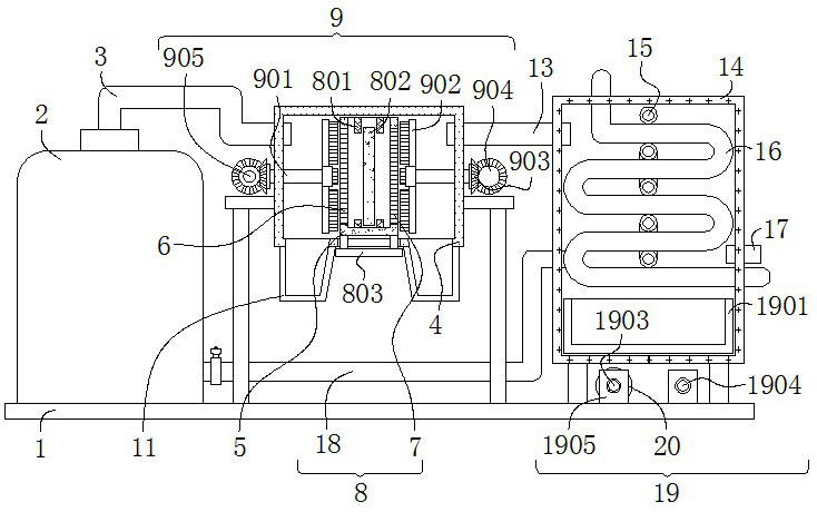
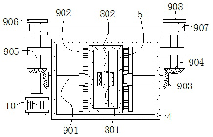
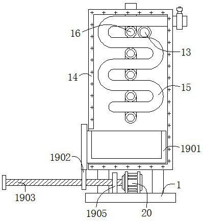
[0053] see Figure 1-8 , the present invention provides a technical solution: a bottom sludge immobilization disposal device, comprising a bottom plate 1, an industrial furnace body 2, a first smoke inlet pipe 3, a connecting cylinder 4, a filter frame 5, a first filter screen 6, a second Filter screen 7, installation mechanism 8, anti-clogging mechanism 9, first motor 10, collecting tank 11, second sealing plate 12, second smoke inlet p


PUM


Abstract

The invention discloses a hot flue gas treatment device and method for an industrial furnace. The hot flue gas treatment device comprises a bottom plate directly placed on the ground. Meanwhile, the right end of the first smoke inlet pipe is mounted at the left upper end of the connecting cylinder; the box body is fixedly connected to the right upper end of the industrial furnace body; the filter frame of which the front-view longitudinal section is of a concave structure is placed in the middle end of the connecting cylinder; the mounting mechanism is arranged on the filtering frame; and the anti-blocking mechanism is arranged on the connecting cylinder. According to the hot flue gas treatment device for the industrial furnace and the treatment method, the filter screen can be conveniently cleaned, the filter screen is prevented from being blocked during purification, the purification speed is increased, the purification assembly is easily mounted and dismounted, meanwhile, condensed water can be conveniently collected and recycled during flue gas waste heat recovery, and the environment-friendly effect is achieved. And pure oxygen or liquid oxygen can be heated during waste heat recovery.

Description


Claims


Application Information

Patent Timeline
Owner 陕西备晟科技有限公司
Why Eureka
Try Eureka