Machining block, machining block holder, and method for positioning machining block
A positioning method and a technology for holding components, which are applied to metal processing machinery parts, positioning devices, metal processing equipment, etc., can solve the problems of material waste of processing blocks, and achieve the effect of reducing misprocessing or material waste
- Summary
- Abstract
- Description
- Claims
- Application Information
AI Technical Summary
Benefits of technology
Problems solved by technology
Method used
Image

Examples
no. 1 approach
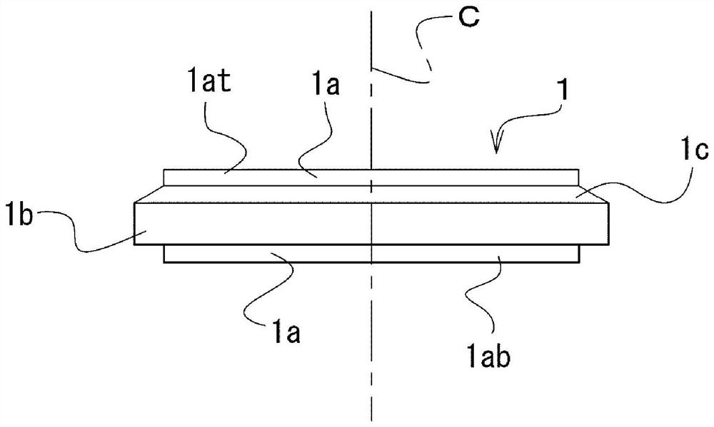
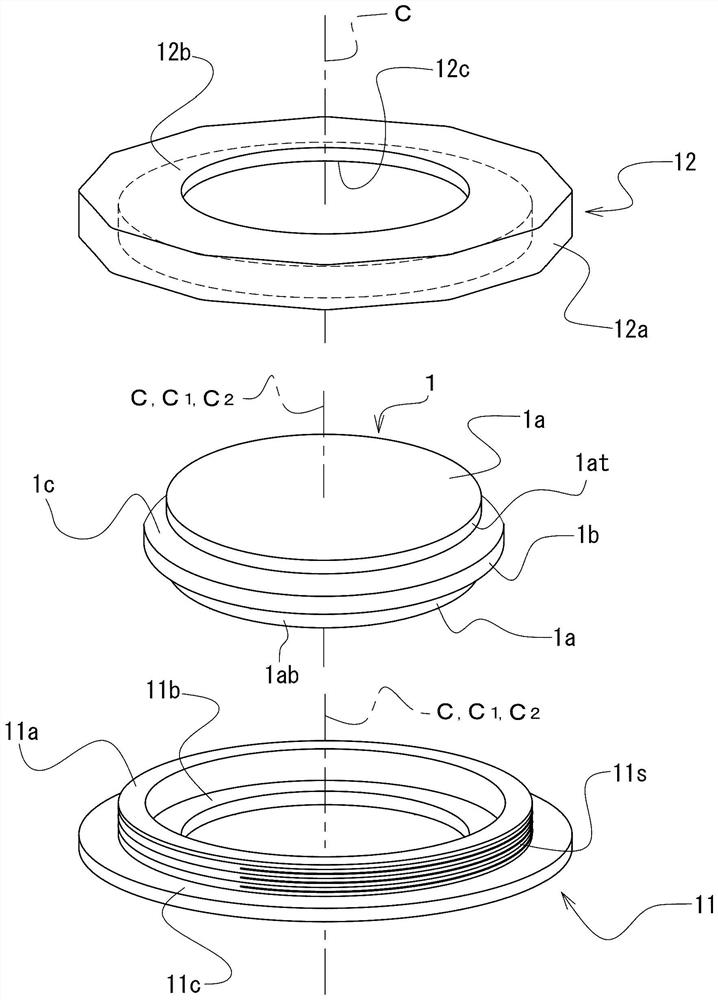
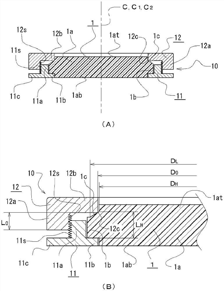
[0050] Figure 1 ~ Figure 3 The block 1 for processing which concerns on 1st Embodiment of this invention is shown in . figure 1 is the front view of block 1 for processing, figure 2 It is an annular holding member 10 (refer to image 3 ) is a perspective view of the storage-side holding member 11 and the pressing-side holding member 12 . in addition, image 3 Middle (A) is a cross-sectional view showing a state in which the processing block 1 is held by the storage-side holding member 11 and the pressing-side holding member 12 in a state cut along a plane including the axis center of the processing block 1 . in addition, image 3 Middle (B) is enlarged representation image 3 A cross-sectional view of part of (A).
[0051] In this processing block 1, a cylindrical processed portion 1a and a flange portion 1b are integrally formed, wherein the flange portion 1b is disposed at the center of the processed portion 1a and has a diameter larger than that of the processed porti
no. 2 approach
[0071] Figure 5 It relates to the second embodiment, which shows that the same processing block 1 as the first embodiment is held in a state different from the first embodiment as a processing block in a cut state including the axis C of the processing block 1 . A cross-sectional view of the state in the annular holding member 20 of the piece. The pressing-side holding member 22 of the second embodiment of the pressing block 1 is formed of an engaging main body portion 22a and a pressing flange portion 22b similarly to the pressing-side holding member 12 of the first embodiment. The facing peripheral edge portion 22c of the pressing flange portion 22b according to the second embodiment is formed by the inner surface of a cone which is a shape overlapping the holding surface 1c of the machining block 1 .
[0072] In addition, regarding the facing peripheral edge portion 22c in this case, when it is formed into a conical shape overlapping with the holding surface 1c, the inclinat
no. 3 approach
[0078] Figure 7 shows the block 3 for processing according to the third embodiment, wherein, Figure 7 Middle (A) is a perspective view of block 3 for processing, Figure 7 Middle (B) is a front view of the block 3 for processing.
[0079] The processing block 3 is formed as follows: no figure 1 The shape of the upper side protrusion 1at which protrudes upward from the holding surface 1c in the to-be-processed part 1a of the processing block 1 which concerns on 1st Embodiment is shown in . That is, a flange portion 3b is formed on the upper end portion of the portion to be processed 3a, and a holding surface 3c formed of an inclined surface is provided on the upper surface of the flange portion 3b. Therefore, the holding surface 3c is formed by an inclined surface provided between the top surface of the processed portion 3a and the side surface of the flange portion 3b. It should be noted that the holding surface 3 c may also be configured such that its lower end portion is
PUM
 Abstract
Description
Claims
Application Information
 - R&D Engineer
- R&D Manager
- IP Professional
- Industry Leading Data Capabilities
- Powerful AI technology
- Patent DNA Extraction
Browse by: Latest US Patents, China's latest patents, Technical Efficacy Thesaurus, Application Domain, Technology Topic.
© 2024 PatSnap. All rights reserved.Legal|Privacy policy|Modern Slavery Act Transparency Statement|Sitemap