Weld joint detection device for square steel welding

A technology for welding seam detection and detection components, which is applied to welding equipment, welding equipment, auxiliary devices, etc., can solve the problems that the detection rod is easy to shift and inconvenient to detect, and achieve functional improvement, adaptability improvement, and guarantee The effect of stability

Inactive Publication Date: 2022-07-05
CHANGZHOU INST OF MECHATRONIC TECH
View PDF0 Cites 0 Cited by
  • Summary
  • Abstract
  • Description
  • Claims
  • Application Information

AI Technical Summary

Benefits of technology

This patented technology allows for easy mountings or modifications onto plain-steel structures without affecting their function. It achieves this by combining certain components together into one unit called the top frame body/lower frame body (TBU). These units fit tight around corners of these structure parts like rectangular pipes, allowing them to stay secure even when subjected to external forces such as winds. A settable locating system helps maintain stable placement while also providing precise location measurement capabilities. Additionally, there may have been improvements over previous designs due to better design features. Overall, it provides technical benefits including enhanced versatility, ease of use, and increased efficiency in testing new products.

Problems solved by technology

The technical problem addressed in this patented text relating to improving the accuracy and efficiency during weld defects testing involves creation of a better way to inspect flat steel without having to constantly move around with one's hands while holding the inspector stickers at their ends instead of carrying them along easily over uneasy surfaces such as slipways.

Method used


Image

  • Weld joint detection device for square steel welding
  • Weld joint detection device for square steel welding
  • Weld joint detection device for square steel welding

Examples


Embodiment Construction

[0037] The technical solutions in the embodiments of the present invention will be clearly and completely described below with reference to the accompanying drawings in the embodiments of the present invention. Obviously, the described embodiments are only a part of the embodiments of the present invention, but not all of the embodiments. Based on the embodiments of the present invention, all other embodiments obtained by those of ordinary skill in the art without creative efforts shall fall within the protection scope of the present invention.

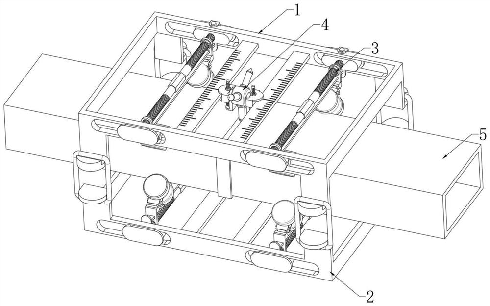
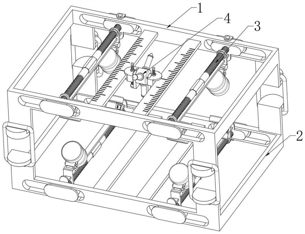
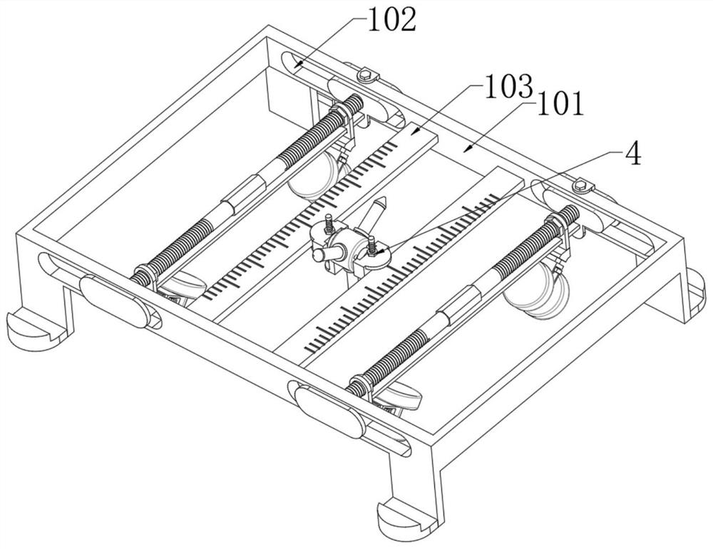
[0038] The present invention provides such as Figure 1-Figure 10 A welding seam detection device for square steel 5 welding is shown, including an upper frame body 1, a lower frame body 2, a positioning assembly 3, a detection assembly 4 and a square steel 55, and a lower frame body 2 is arranged below the upper frame body 1, and the upper frame body 2 is provided. A detection assembly 4 is arranged in the middle of the body 1, a positi


PUM


Abstract

The invention discloses a welding seam detection device for square steel welding, and relates to the technical field of welding equipment.The welding seam detection device comprises an upper frame body, a lower frame body, positioning assemblies, a detection assembly and square steel, the lower frame body is arranged below the upper frame body, the detection assembly is arranged in the middle of the upper frame body, and the positioning assemblies are arranged in the upper frame body and the lower frame body; square steel is arranged between the upper frame body and the lower frame body. According to the device, the upper frame body, the lower frame body, the positioning assembly and the detection assembly are arranged, the upper frame body and the lower frame body are matched, the device can be installed on the outer side of square steel in a sleeving mode, the distance between the upper frame body and the square steel and the distance between the lower frame body and the square steel can be adjusted through the positioning assembly, and therefore the installation stability of the device is guaranteed; the detection assembly can detect the welding seam of square steel, and the detection assembly slides in the upper frame body, so that the sliding stability of the detection rod in the detection process can be ensured, and the detection precision is further ensured.

Description


Claims


Application Information

Patent Timeline
Owner CHANGZHOU INST OF MECHATRONIC TECH
Why Eureka
Try Eureka