Fast automatic processing method utilized in lathe and milling machine for large thin wall part with cylindrical grids

An automatic processing and grid technology, applied in the field of mechanical cutting, can solve the problems of low rigidity and strength, low yield, low production efficiency, etc., and achieve the effect of simple processing technology, meeting technical requirements and high production efficiency

Inactive Publication Date: 2005-01-12
沈阳工业学院
View PDF0 Cites 25 Cited by
  • Summary
  • Abstract
  • Description
  • Claims
  • Application Information

AI Technical Summary

Benefits of technology

This innovation makes it possible for small scale welded steel plates (SHPBs) used during manufacturing processes to be processed faster than traditional methods such as rolling or machining.

Problems solved by technology

Technics: In this patented process, it's challenged by making small circular grinding tools that can accurately handle these types of materials without causing damage or distortion in their final dimensions. Current methods have limitations such as slow down producing efficacy, requiring expensive equipment, lack precision, poor performance, etc., which makes them hard to achieve good results.

Method used


Image

  • Fast automatic processing method utilized in lathe and milling machine for large thin wall part with cylindrical grids
  • Fast automatic processing method utilized in lathe and milling machine for large thin wall part with cylindrical grids
  • Fast automatic processing method utilized in lathe and milling machine for large thin wall part with cylindrical grids

Examples


Embodiment Construction

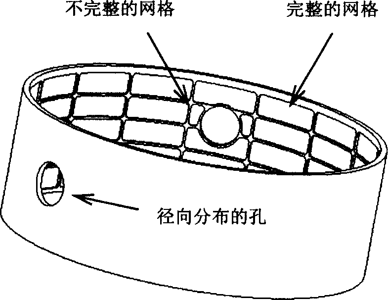
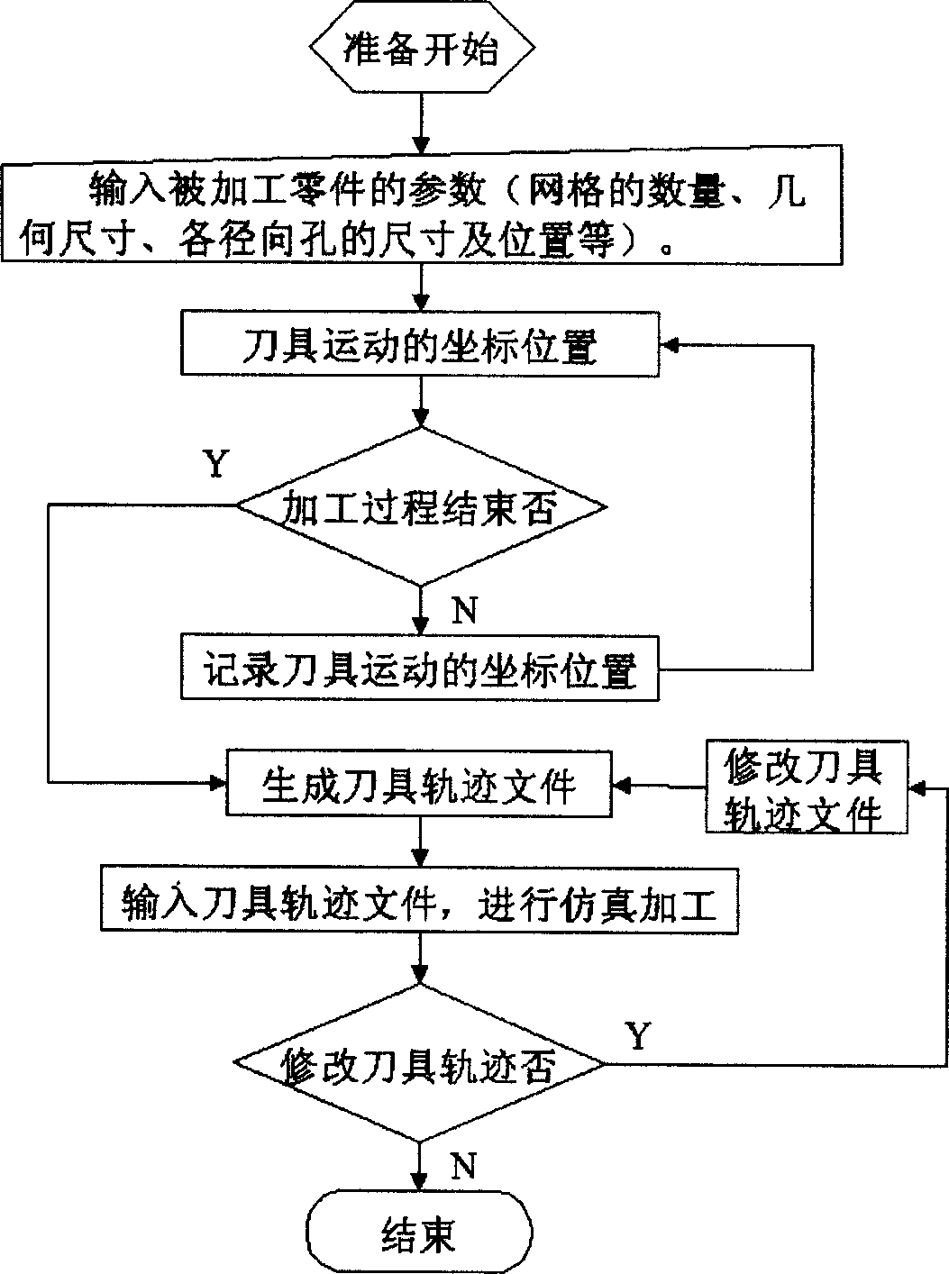
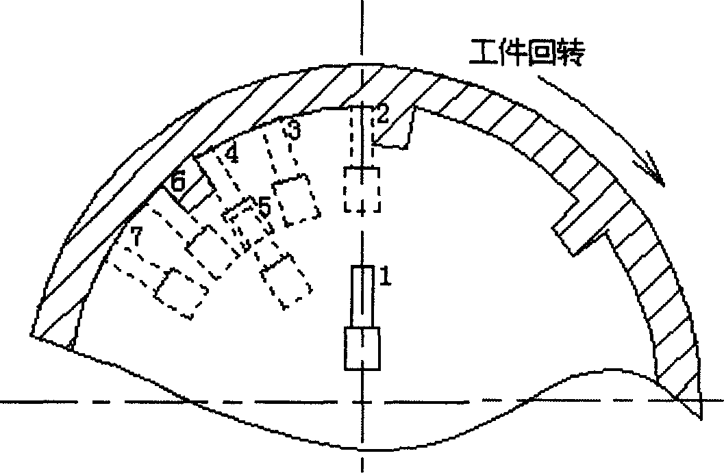
[0011] The technical method of the high-speed turning and milling of the cylindrical mesh of the present invention is further illustrated in conjunction with examples. For example, processing, a thin-walled part of a rotating body with a diameter of 1500mm, a wall thickness of 6mm, and a height of 450mm. Such as figure 1 As shown, the inner surface has a cylindrical grid structure. Using an elevated five-axis linkage processing machine tool, the first step: first process the reference plane, outer circle and inner hole of the part; the second step: forming and processing the cylindrical grid, using a φ20mm TiN coated four-tooth finger milling cutter, the tool The fast forward speed is 45m / min, the tool speed is 12000r / min, and the cutting feed speed is 2.5mm / s. High-speed wind cooling is adopted, and the wind pressure is 5-6Mpa. At room temperature, the tool continuously processes the cylindrical mesh according to the processing program. The trajectory of the tool moveme


PUM


Abstract

A method for automatically machining the large thin-wall workpiece with lattice on its cylindrical surface by high-speed turning and milling includes such steps as machining reference surface, internal hole and extenal circumference, machining lattice on cylindrical sulface, machining radial holes,and fine finishing. Its computer program is also disclosed.

Description


Claims


Application Information

Patent Timeline
Owner 沈阳工业学院
Why Eureka
Try Eureka