Fluted disc structure of crusher

A pulverizing tooth and pulverizer technology, applied in the application, feed, grain processing and other directions, can solve the problems of material waste and use cost, inconsistent looseness, affecting the pulverization quality, etc., and achieve the effect of simple structure, convenient production, convenient installation and disassembly

Inactive Publication Date: 2010-12-29
天津帝凯维动物营养有限公司
View PDF0 Cites 1 Cited by
  • Summary
  • Abstract
  • Description
  • Claims
  • Application Information

AI Technical Summary

Problems solved by technology

Due to the inconsistent degree of hardness and looseness of the raw materials, raw materials are often stuck to the re

Method used


Image

  • Fluted disc structure of crusher
  • Fluted disc structure of crusher
  • Fluted disc structure of crusher

Examples


Example Embodiment

[0013] In order to further understand the content, features, and effects of the present invention, the following embodiments are given as examples, and detailed descriptions are as follows with accompanying drawings:

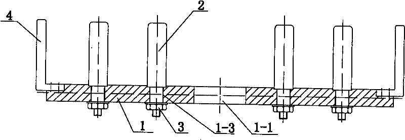
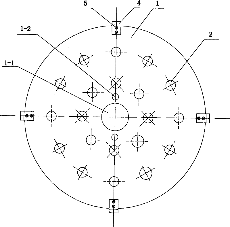
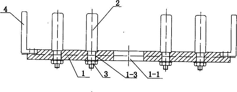
[0014] See figure 1 with figure 2 , A toothed disk structure for a pulverizer, comprising a circular disk body 1, a mounting hole 1-1 and a positioning hole 1-2 arranged in the center of the disk body 1, and a crushing tooth 2. The crushing tooth 2 is detachable Type installation structure, that is, installation holes 1-3 are evenly distributed on the end surface of the circular disc body 1, and the crushing teeth 2 are inserted into the installation holes 1-3, and the crushing teeth are fastened on the other end of the circular disc body 1. The nut 3 is fastened to the circular disk body 1, and crushing teeth 4 are evenly distributed on the outer circumference of the circular disk body 1, and the crushing teeth 4 are fastened to the circular disk body 1 by a fastene


PUM


Abstract

The utility model relates to a fluted disc structure of a crusher, which comprises a round disc body, mounting holes, a positioning hole and crushing teeth, wherein the mounting holes, the positioning hole are formed in the center of the disc body. The fluted disc structure is characterized in that the crushing teeth adopt demountable mounting structure, i.e. the mounting holes are uniformly distributed on one end surface of the round disc body and the crushing teeth are inserted into the mounting holes; on the other end surface of the round disc body, the crushing teeth are fastened with the round disc body through fastening pieces; and the crushing teeth are uniformly distributed on the outer circumferential edge of the round disc body, and are fastened with the round disc body through the fastening pieces. By adopting the structure of the utility model, if one or more crushing teeth are damaged during use, the damaged crushing tooth/teeth can be independently replaced and the original disc body is not changed, thereby saving raw material and reducing use cost. Additionally, the utility model has the advantages of simple structure, easy manufacture, convenient installation and dismantling, etc.

Description


Claims


Application Information

Patent Timeline
Owner 天津帝凯维动物营养有限公司
Why Eureka
Try Eureka