Sliding-type portable digital communication apparatus

a digital communication and portable technology, applied in the field of portable digital communication apparatuses, can solve the problems of high possibility of loss of camera lens module, inconvenient use of photographing subject, and user's inability to help changing pose or position, etc., to achieve the effect of convenient use of photographing

Inactive Publication Date: 2005-03-31
SAMSUNG ELECTRONICS CO LTD
View PDF6 Cites 33 Cited by
  • Summary
  • Abstract
  • Description
  • Claims
  • Application Information

AI Technical Summary

Benefits of technology

The technical effect of this patented device was that it solves issues with existing devices such as cameras or scanners by making them easier to use on both portrait and landscape shots.

Problems solved by technology

This patents describes different technical problem addressed in this patented design: how to improve upon existing devices (such as traditional mobile phone) without compromising its functionality when worn over longer distances due to being bulky or carrying heavy objects. Existing solutions involve adding more components within the device's casing structure, making them difficult to use during long periods of time because they require users to put up multiple items separately. There is thus a desire towards developing a solution where cameras attached directly onto the exterior surface of the device itself instead of attaching externals thereto.

Method used


Image

  • Sliding-type portable digital communication apparatus
  • Sliding-type portable digital communication apparatus
  • Sliding-type portable digital communication apparatus

Examples


Embodiment Construction

[0022] Hereinafter, preferred embodiments of the present invention will be described with reference to the accompanying drawings. In the following description, a detailed description of known functions and configurations incorporated herein will be omitted when it may make the subject matter of the present invention rather unclear.

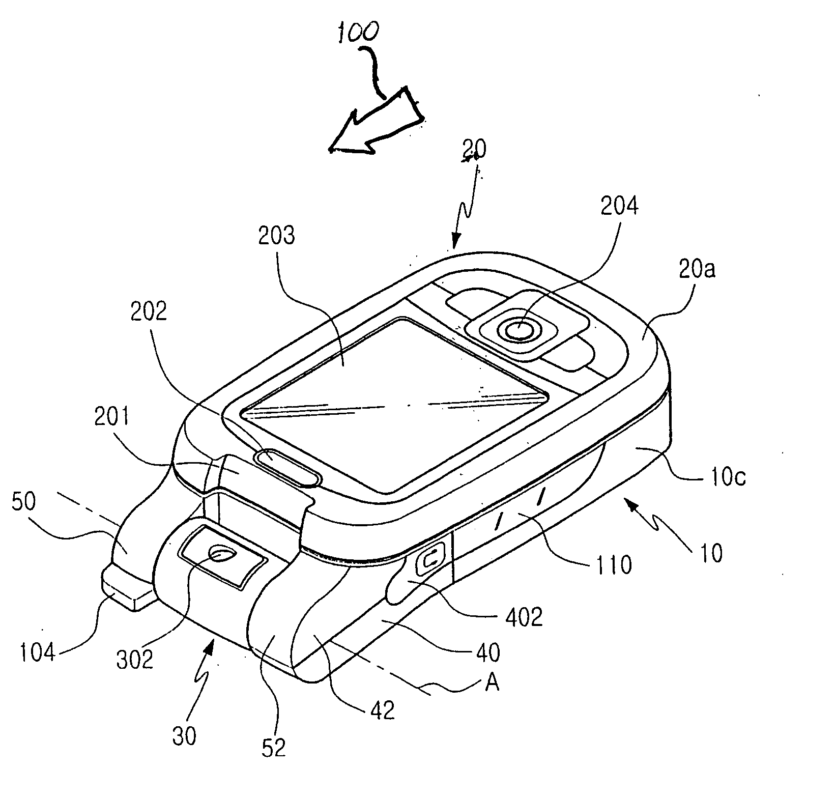
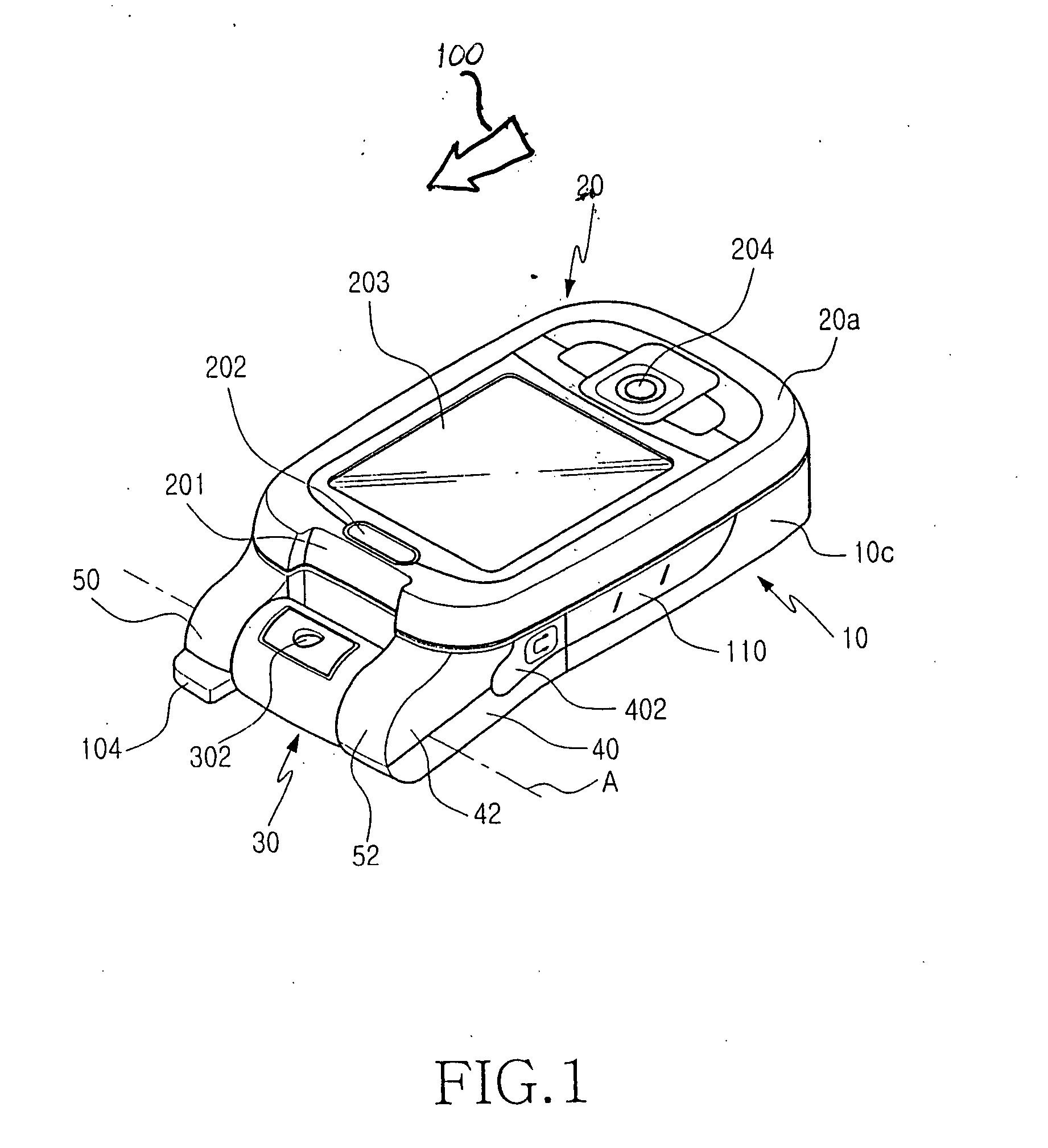
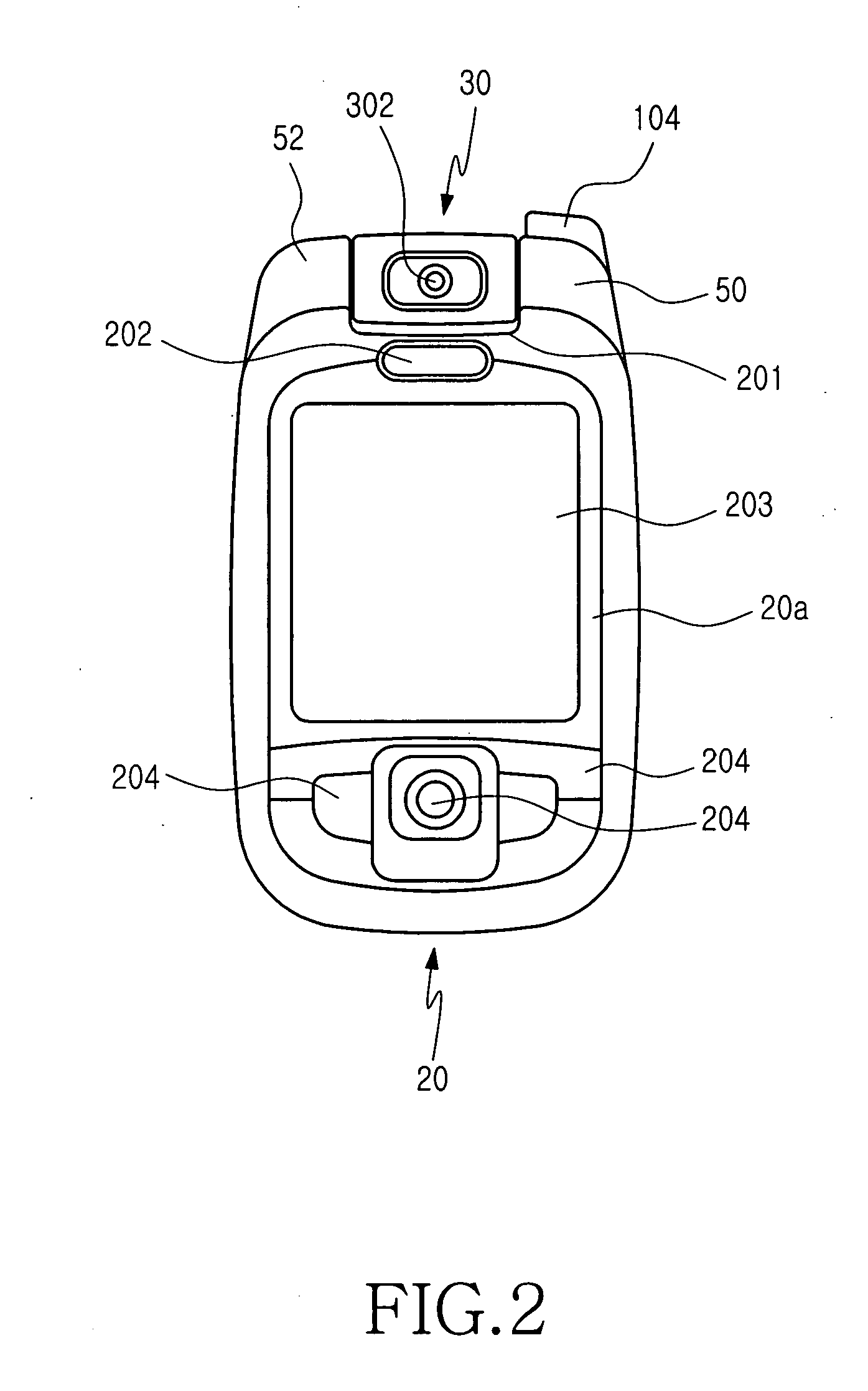
[0023] As shown in FIGS. 1 through 6, a portable digital communication apparatus according to a preferred embodiment of the present invention includes a body housing 10, a sliding housing 20 sliding on an upper surface 10a (FIG. 3) of the body housing 10 in a longitudinal direction of the apparatus, angled housings 40 and 42 extending from two corners of one side of the body housing 10 in an inclined direction with respect to the body housing 10, a pair of connecting arms 50 and 52 extending in the inclined direction in which the angled housings 40 and 42 extend, and a rotatable lens housing 30 disposed between the connecting arms 50 and 52 in such a manner


PUM


Abstract

A sliding-type portable communication apparatus includes a body housing; a sliding housing sliding on an upper surface of the body housing while being in contact with the body housing; first and second angled housings, each of the first angled housings extending from one corner of one side of the body housing in an inclined direction gradually going far from a lower surface of the sliding housing, each of the second angled housing having a first surface and a second surface, the first surface being in contact with the first angled housing while extending in the inclined direction, and the second surface being opposite to the first surface and in contact with the sliding housing; a pair of connecting arms, each of which extends from an end of one of the second angled housings in the inclined direction; and a rotatable lens housing disposed between the connecting arms and having a camera lens, the camera lens being oriented in a direction passing through the lower surface of the sliding housing when the sliding housing has not been moved a predetermined distance, and the camera lens being oriented in a direction passing through the upper surface of the body housing when the sliding housing has been moved.

Description


Claims


Application Information

Patent Timeline
Owner SAMSUNG ELECTRONICS CO LTD
Why Eureka
Try Eureka