Process for producing low-molecular olefins by pyrolysis of hydrocarbons

a technology of hydrocarbon pyrolysis and hydrocarbons, which is applied in the field of petrochemical industry, can solve the problems of increasing the yield of less valuable acetylene, overheating the cracking tube, and reducing the productivity of the pyrolysis plant, and achieves the effect of reducing the energy consumption of process conducting

Inactive Publication Date: 2005-06-23
COOLBROOK
View PDF1 Cites 4 Cited by
  • Summary
  • Abstract
  • Description
  • Claims
  • Application Information

AI Technical Summary

Benefits of technology

Gas turbine engines are used more efficiently when it's being driven through reactors than before. However, there may still be some parts that require further treatment after they have been done with them due to high temperatures caused during operation or other factors such as poor air quality (which affects cooler compressor performance). This requires an effective method called prewashing where incoming streams are introduced into one part while another part remains warm enough to allow vaporization without losing any useful work on their own.

Problems solved by technology

Technological Problem: Existing techniques for thermally decompositing hydrogen sulfide compounds during conversion between different chemical species involve complex steps involving multiple components including coolants, compressors, and turbulators. These technical problem addressed by the patents include improving efficiency without causing damage caused by overreactant chemistry within the equipment itself, particularly if large amounts of water pass through the system.

Method used


Image

  • Process for producing low-molecular olefins by pyrolysis of hydrocarbons
  • Process for producing low-molecular olefins by pyrolysis of hydrocarbons
  • Process for producing low-molecular olefins by pyrolysis of hydrocarbons

Examples


Embodiment Construction

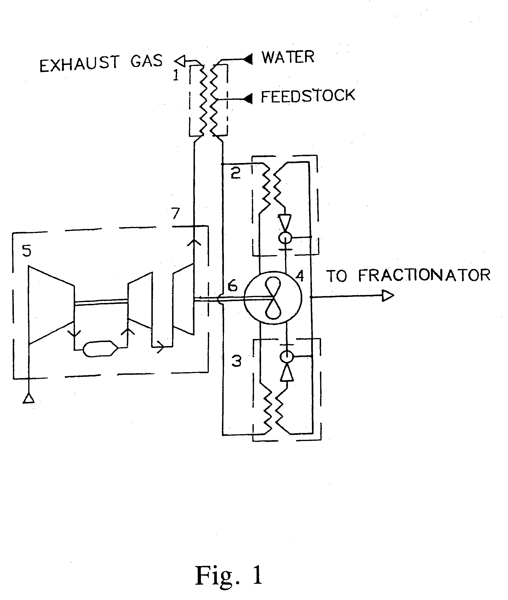
[0054] The installation (FIG. 1) for realization of the process includes preheater 1, apparatuses 2 and 3 for quenching of product stream, reactor 4, gas-turbine engine 5 connected with reactor 4 by shaft 6, and with the preheater 1 by exhaust pipe 7.

[0055] Preheating a feedstock and steam-diluent in the first stage is carried out in the preheater 1. The hydrocarbon feed form outside source (not shown in drawings) is conveyed by pressure into the preheater 1 configured as a shell-tube heat exchanger. The exhaust gas from the gas-turbine engine 5 is discharged into the intertubular space of this heat exchanger. From an outside source (not shown in drawings) water is conveyed by pressure into the preheater where the water it is evaporated, and resulting steam-diluent is mixed with the hydrocarbon feed.

[0056] Preheating a feedstock and steam-diluent in the second stage is carried out in the apparatuses 2 and 3 for quenching of product stream by utilization of heat of product stream leav


PUM


Abstract

Process for producing low-molecular olefins by pyrolysis of hydrocarbons comprising mixing of feedstock with steam-diluent, preheating the resulting mixture, rapid heating the said mixture up to pyrolysis temperature and maintaining this temperature inside reactor during residence time, quenching product stream and subsequent fractionation of products. The reactor has an annular work cavity where stationary blades and rotatable work blades are located. A ring vortex flow is created and maintained in the work cavity when the work blades are rotated. A heat needed for pyrolysis is generated due to hydrodynamic drag of rotated work blades. Heating the mixture up to pyrolysis temperature is performed by mixing with hot process stream recirculated in the work cavity for a negligible time in comparison with the residence time. The process enables increase of the low-molecular olefins yield.

Description


Claims


Application Information

Patent Timeline
Owner COOLBROOK
Why Eureka
Try Eureka