Solid-state light sources for curing and surface modification
a technology of solid-state light sources and light sources, which is applied in the direction of light sources, semiconductor devices, lighting and heating apparatus, etc., can solve the problems of high-power lamps that also require cooling and heat rejection systems, materials (for example, substrates or coating components) may be heat sensitive and damaged by thermal treatment, and achieve high stability of spectral output , improve the lifetime of arrays, increase the flexibility of photochemical processes
- Summary
- Abstract
- Description
- Claims
- Application Information
AI Technical Summary
Benefits of technology
Problems solved by technology
Method used
Image

Examples
embodiment 10
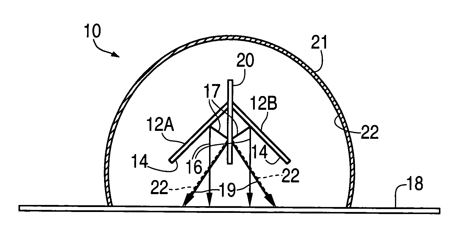
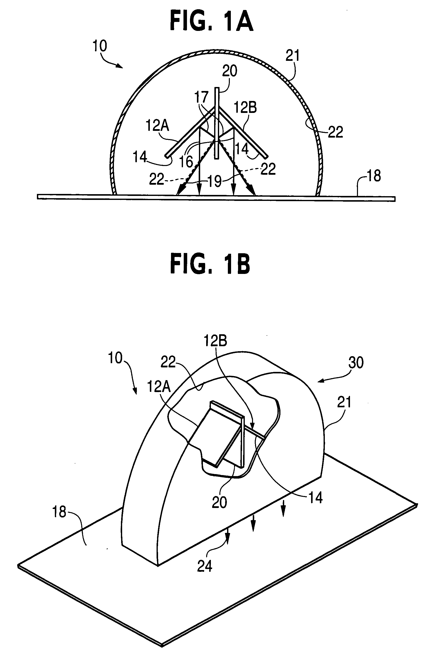
[0059] The pair of light emitting arrays 12A and 12B are illustrated as square flat panels. The light emitting arrays are comprised of a plurality of devices, such as LEDs, which emit radiation in the ultraviolet range but the invention is not limited thereto with a suitable construction being described below in conjunction with FIG. 1C. For example, in a high power irradiation apparatus in accordance with the embodiment 10 of FIGS. 1A and 1B, the arrays 12A and 12B may respectively be an array of 40 LEDs as described in FIG. 1C which individually emit at 400 mW at 405 nm mounted on an integrated circuit of approximately 1 square cm. The other radiation source 12B may, without limitation, be an array of 40 LEDs as described below emitting 100 mW at 390 nm mounted on an integrated circuit of approximately 1 square cm. Additionally, the optical mixing element 20 may be semi-reflective mirror which substantially equally splits the emission from the rays 16 into reflected rays 19 and trans
first embodiment
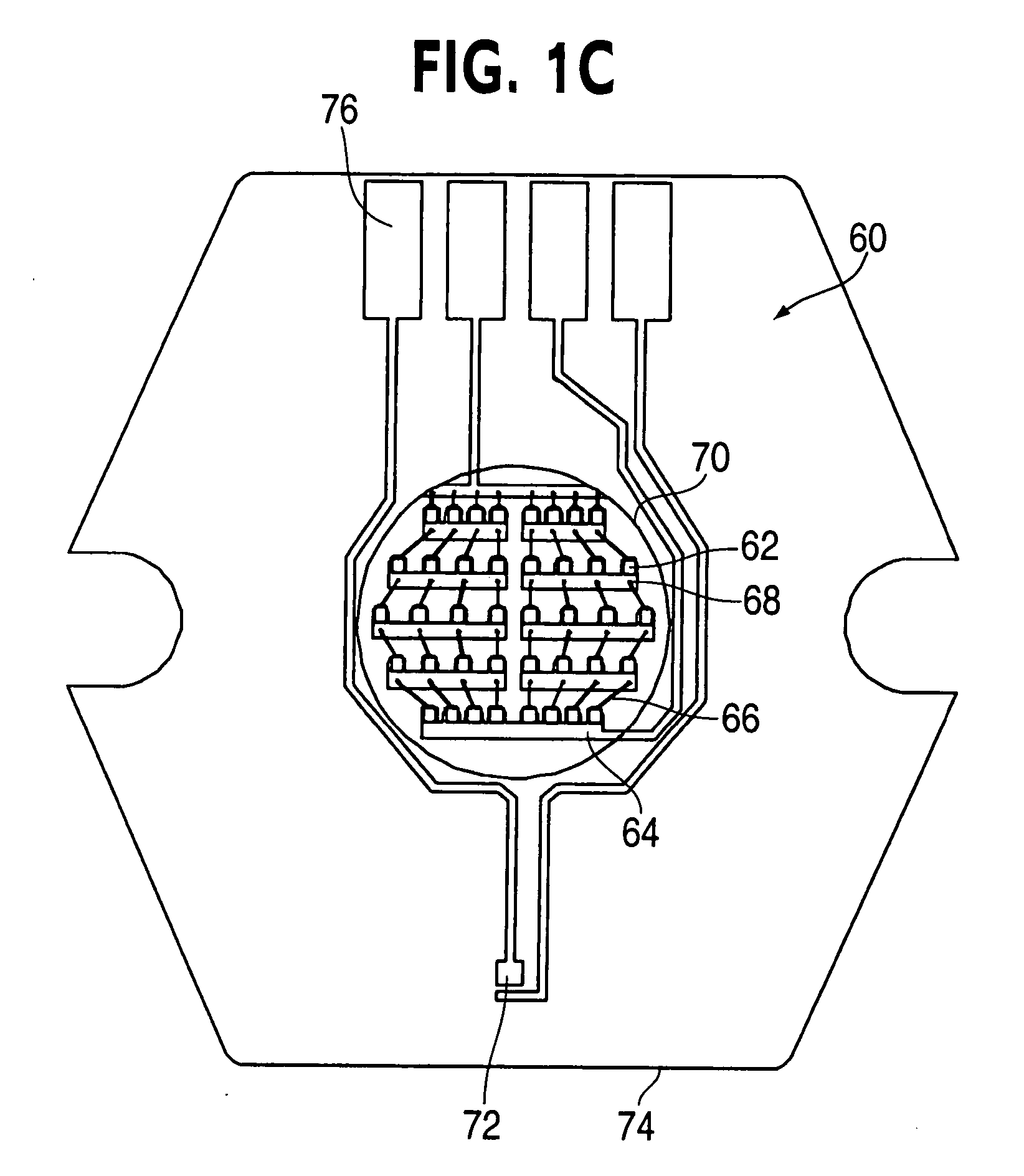
[0060]FIG. 1C illustrates a suitable construction for the light emitting solid state arrays 12A and 12B with a scale of approximately 5:1 for the first embodiment as described above and in the embodiments as described below. The array 60 is comprised of 40 LEDs 62. A lower bus bar 64 has a group of 8 LEDs mounted thereon. Each of the LEDs 62 mounted on the lower bus bar 64 are in turn coupled by a wire 66 by means of wire bonds 68 which connect the wire extending from the individual LEDs to four upper bus bars 64 on which 4 LEDs are mounted. A lens 70 focuses light emitted by the individual LEDs 62 toward the optical mixer 20. A thermal sensor 72 is utilized to provide temperature control for the LED array 60. The LED array 60 is mounted on a hexagonal substrate 74. Electrical terminals 76 are mounted on the hexagonal substrate 74 to provide suitable electrical contacts for electrical power of the array.
[0061] The light source represented by the light emitting solid state arrays 12A an
embodiment 700
[0078]FIG. 19 shows the simulated irradiance of the embodiment 700 of FIG. 18 on the irradiated surface 18. The radiance pattern of the beam shows a ring-like pattern near the peak irradiance. This pattern is due to the placement of the radiation sources 332A-332D in a circle about the optical mixers 350. As described above with respect to other embodiments, the internally reflective curved cylindrical housing, controller, cooling system and target surface have been emitted.
[0079]FIGS. 20 and 21 show eleventh and twelfth embodiments 800 and 900 of the present invention that utilize elongated linear arrays of diodes 12A′ and 12B′ with the embodiment 800 having elongated optical mixer 20′ which is a semitransparent mirror and the embodiment 900 utilizing an optical mixer 902 which is a prism for splitting and mixing beams from the arrays 12A′ and 12B′ using internal reflection rather than reflection from a mirror. As described above with respect to other embodiments, the internally refle
PUM
| Property | Measurement | Unit |
|---|---|---|
| Fraction | aaaaa | aaaaa |
| Fraction | aaaaa | aaaaa |
| Power | aaaaa | aaaaa |
Abstract
Description
Claims
Application Information
 - R&D Engineer
- R&D Manager
- IP Professional
- Industry Leading Data Capabilities
- Powerful AI technology
- Patent DNA Extraction
Browse by: Latest US Patents, China's latest patents, Technical Efficacy Thesaurus, Application Domain, Technology Topic.
© 2024 PatSnap. All rights reserved.Legal|Privacy policy|Modern Slavery Act Transparency Statement|Sitemap