Machine element part with ic tag

Inactive Publication Date: 2006-12-28
NTN CORP
View PDF8 Cites 18 Cited by
  • Summary
  • Abstract
  • Description
  • Claims
  • Application Information

AI Technical Summary

Benefits of technology

[0035] Since the IC tag equipped mechanical component of the present invention is such that a plurality of IC tags are attached to a machine component or to a machine component and an accessory with division made therebetween and different information is stored in those IC tags, the IC tag can be mounted with no difficulty while the storage capacity of the IC tag is increased and, also, reading or writing of information from or in the IC tag, respectively, can be facilitated.
[0036] Where the machine component includes a rotatable component part and the plural IC tags are attached to the rotatable component part and positioned in symmetrical relation with each other about an axis of rotation, it is possible to avoid disruption of the balance of rotation.
[0037] Where one of the IC tags has recorded therein handling instructions associated with the machine component, contents of the handling manual can be presented easily and, also, the handling manual can be r

Problems solved by technology

Although the foregoing problems have been discussed as being found where the machine component is a bearing assembly, problems similar to those discussed above may be equally found with any other machine components such as, for example, shaft couplings and motors that tend to deteriorate naturally with passage of time of use.
When it comes to attachment of an IC tag to a machine component, not only is the site of placement limited, but the outside dimensions of the IC tag that can be attached to the machine component is limited.
However, if a small IC tag is used, the storage capacity thereof is indeed small and it may occur that a sufficient amount of information cannot be stored in it.
The use of a large IC tag to increase the storage capacity will result in such problems and inconveniences that part of the IC tag may protrude outwardly to form an obstacle to the neighboring parts and that the presence of a hole or recess for accommodating the IC tag may decrease the strength of the machine component.
Where the IC tag is attached to the machine component, it is desirable to mount the IC tag on a portion of the machine component or its peripheral part that does not affect the strength and the precision, but where that portion of the machine component or its peripheral part is a rotatable element such as, for example, a roller retainer or cage employed in a rolling bearing ass

Method used


Image

  • Machine element part with ic tag
  • Machine element part with ic tag
  • Machine element part with ic tag

Examples


Embodiment Construction

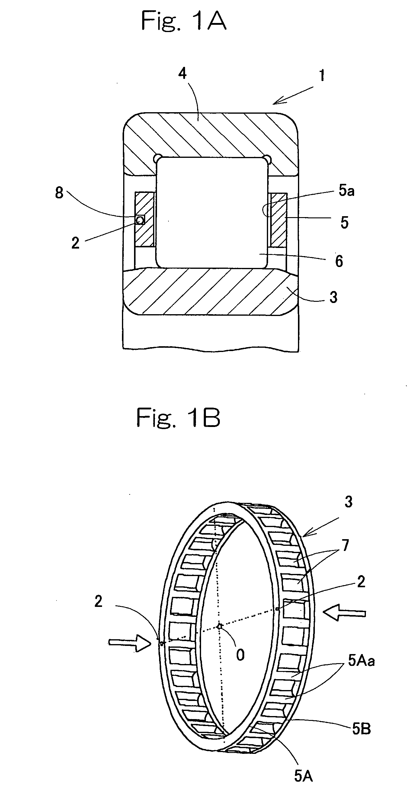
[0056] A first preferred embodiment of the present invention will be described in detail with particular reference to FIGS. 1A to 3. The IC tag-equipped machine component shown therein is in the form of a rolling bearing assembly 1, which forms a machine component, having a plurality of IC tags 2 attached thereto. The rolling bearing assembly 1 is of a type including a row of rolling elements 6 retained by a roller retainer 5 and interposed between an inner race 3 and an outer race 4. No sealing member is employed and the roller retainer 5 is exposed to the outside through opposite annular open ends of the rolling bearing assembly 1. Although the rolling bearing assembly 1 may be a cylindrical roller bearing, a tapered roller bearing, a deep groove ball bearing or an angular contact ball bearing, the cylindrical roller bearing is employed in the illustrated embodiment as an example of the rolling bearing assembly 1. Also, although the inner race 3 is shown as a collarless type and the


PUM


Abstract

To provide a machine component with an IC tag affixed thereto, in which with the IC tag having an increased storage capacity, the IC tag can be mounted with no difficulty and, also, reading or writing of information from or in the IC tag, respectively, can be facilitated. A plurality of IC tags 2 are attached to a machine component, which forms a part of a rolling bearing assembly 1, or to a machine component and an accessory with division made therebetween. Those plural IC tags 2 have different information stored therein. Where the machine component is a retainer incorporated rolling bearing assembly 1, those plural IC tags are attached to a roller retainer 5 at respective locations symmetrical with each other about the axis O of rotation thereof.

Description


Claims


Application Information

Patent Timeline
Owner NTN CORP
Why Eureka
Try Eureka