Camera module package

a technology of camera module and camera module, applied in the field of camera module package, can solve the problems of limited circuit processing, inability to use the camera as an image sensor, and inability to process circuits in parallel, so as to improve image quality, prevent foreign material infiltration, and simplify assembly process

Inactive Publication Date: 2007-06-28
SAMSUNG ELECTRO MECHANICS CO LTD
View PDF13 Cites 41 Cited by
  • Summary
  • Abstract
  • Description
  • Claims
  • Application Information

AI Technical Summary

Benefits of technology

The technical effect of this patented invention is that it provides a simplified way to make cameras modules by reducing their size while maintaining good image quality. This makes them easier to assemble without requiring many parts or having to be kept cleaned up after use.

Problems solved by technology

This patent describes a problem with traditional camera modules that use a chip scale package (CCP) approach. These modules have issues with the assembly process and the difficulty in removing extraneous materials from the module's interior. Additionally, these modules cannot accommodate multiple functions without requiring larger packages.

Method used


Image

  • Camera module package
  • Camera module package
  • Camera module package

Examples


Embodiment Construction

[0034]Preferred embodiments of the present invention will now be described in detail with reference to the accompanying drawings.

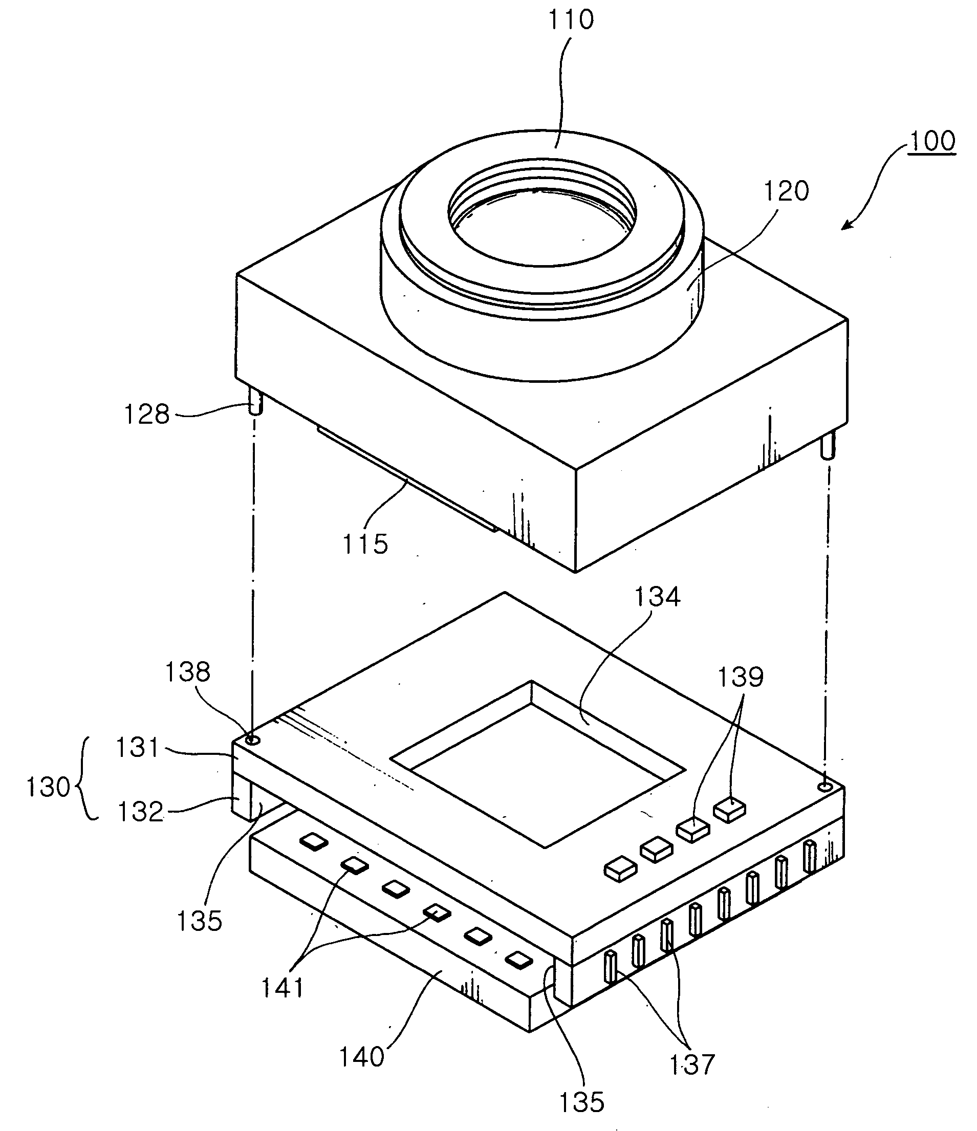
[0035]FIG. 3 is an exploded perspective view illustrating a camera module package according to the present invention, and FIG. 4 is a sectional view illustrating the camera module package according to the present invention.

[0036]As shown in FIGS. 3 and 4, the camera module package 100 includes a lens barrel 110, a housing 120, a substrate 130 and an image sensor 140.

[0037]The lens barrel 110 has a cylindrical shape and has a predetermined dimension of inner space where at least one lens 112 is disposed along an optical axis.

[0038]The plurality of lenses 112 disposed in the lens barrel 110 may be spaced apart from another lens in a predetermined interval by a spacer 119.

[0039]The lens barrel 110 has male threads 111 formed on an outer surface thereof and a cap 113 assembled atop. The cap 113 has a light incident hole 113 a perforated in a center thereof and se


PUM


Abstract

The invention relates to a camera module package including a lens barrel having at least one lens therein and an IR filter installed at a lower end thereof. The package also includes a housing having the lens barrel disposed movable in an optical axis direction in an inner hole thereof. The package additionally includes a ceramic substrate attached to a lower end of the housing, the ceramic substrate having an opening formed on an upper surface thereof corresponding to the position of the lens. The package further includes an image sensor electrically connected to a lower part of the ceramic substrate, the image sensor having an image sensing region thereof exposed through the opening of the ceramic substrate. This prevents damaging the components by the adhesive leaking during the assembly, defective products due to infiltration of extraneous material, improves product reliability and reduces manufacturing costs.

Description


Claims


Application Information

Patent Timeline
Owner SAMSUNG ELECTRO MECHANICS CO LTD
Why Eureka
Try Eureka