Light guide plate, light deflecting element configuration and surface light source device

Inactive Publication Date: 2007-09-27
WINTEK CORP
View PDF17 Cites 5 Cited by
  • Summary
  • Abstract
  • Description
  • Claims
  • Application Information

AI Technical Summary

Benefits of technology

The present technology relates to improving how well fluorescent lights go from one section of a transparent material (light conductor) towards another area without forming shadows or glare on other areas around them. This makes it easier for people who work with these materials to see things clearly by reducing their eye strain caused by scattered light patterns near those points where they're looking something like this.

Problems solved by technology

This patented technical problem addressed in this patents relates to improving the efficiency and evenness of light guides used within displays without causing unwanted effects like ghost patterns caused by misalignments during manufacturing processes.

Method used


Image

  • Light guide plate, light deflecting element configuration and surface light source device
  • Light guide plate, light deflecting element configuration and surface light source device
  • Light guide plate, light deflecting element configuration and surface light source device

Examples


Embodiment Construction

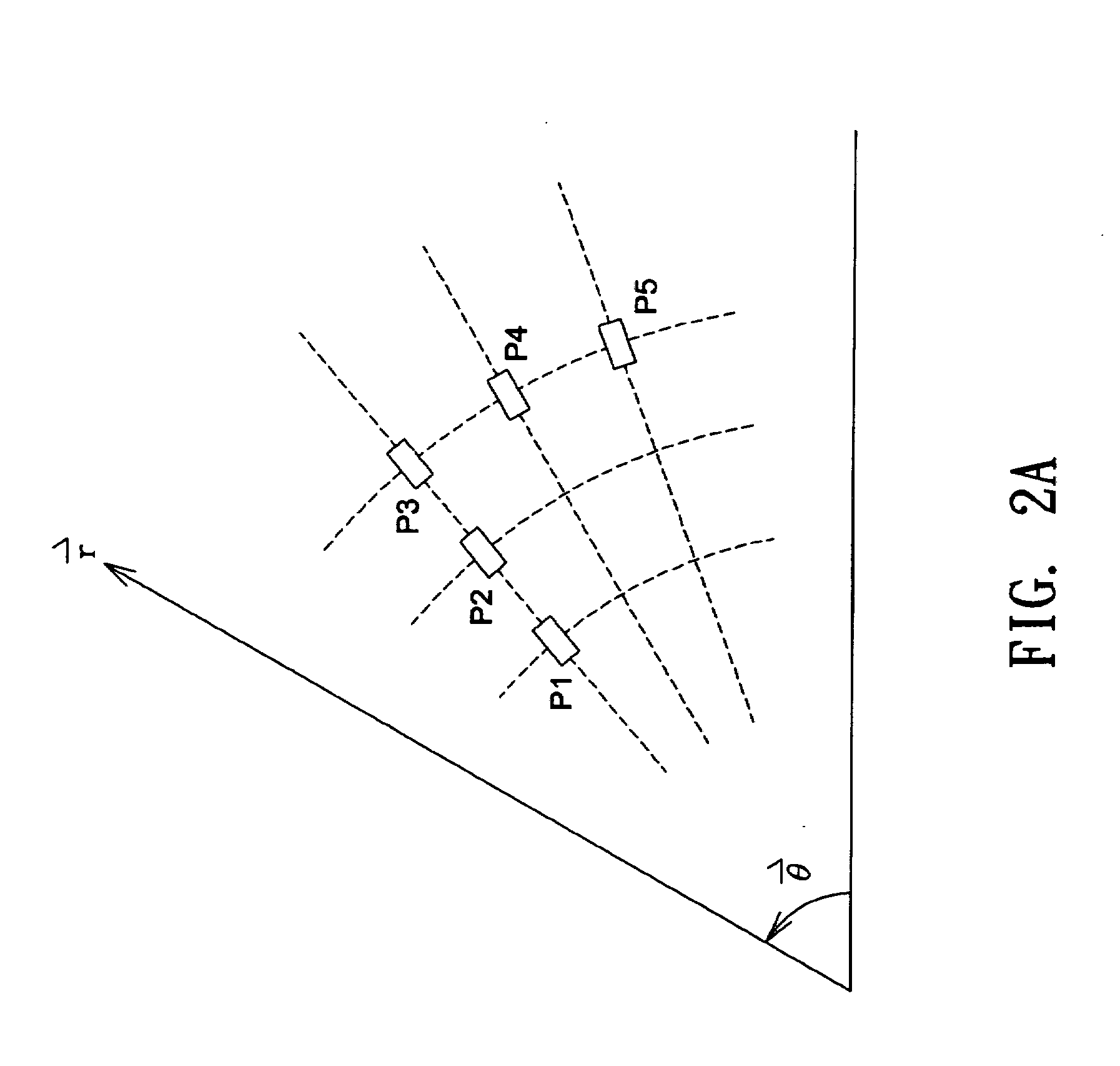
[0027]Herein, the rule for arranging light deflecting elements in a plane is defined as the following before the embodiments of the invention are explained.

[0028]As shown in FIG. 2A, when light deflecting elements are distributed in a polar coordinate plane, an arrangement where light deflecting elements P1, P2, and P3 positioned substantially in a line is defined as “arranging along r direction (radial direction) of the polar coordinate plane”, while an arrangement where light deflecting elements P3, P4, and P5 positioned on the circumference of a concentric circle at different angles θ is defined as “arranging along θ direction (angular direction) of the polar coordinate plane”. On the other hand, as shown in FIG. 2B, when light deflecting elements are distributed in a Cartesian coordinate plane, an arrangement where light deflecting elements Q1, Q2 and Q3 positioned in a horizontal line is defined as “arranging along X-axis direction of the Cartesian coordinate plane”, while light d


PUM


Abstract

A light guide plate includes a base plate and a plurality of light deflecting elements. The light deflecting elements are formed on one surface of the base plate and arranged based on two coordinate axis directions of the surface of the base plate. Each row of the light deflecting elements substantially aligned along one coordinate axis direction has a distribution offset toward the other coordinate axis direction.

Description


Claims


Application Information

Patent Timeline
Owner WINTEK CORP
Why Eureka
Try Eureka