Resin cage for ball bearing

Active Publication Date: 2009-03-19
JTEKT CORP
View PDF12 Cites 6 Cited by
  • Summary
  • Abstract
  • Description
  • Claims
  • Application Information

AI Technical Summary

Benefits of technology

[0017]According to the resin cage for a ball bearing according to the invention, the uniformization of the thickness of the cage of the entire cage can be achieved. Consequently, the deterioration of the flowability of resin at molding thereof and the generation of internal stress can be suppressed properly. Accordingly, the moldability of the cage, which is a resin molded article, can be enhanced.
[0018]In addition, the invention can provide the resin cag

Problems solved by technology

Such a sharp change in the thickness may deteriorate the flowability of resin at injection molding with the result of causing injection-molding defects, such as sink marks and air bubbles.
In addition, the presence of a thickness difference may cause variation in cooling-down time of resin at injection molding with the r

Method used


Image

  • Resin cage for ball bearing
  • Resin cage for ball bearing
  • Resin cage for ball bearing

Examples


Embodiment Construction

[0028]Hereinafter, a resin cage for a ball bearing according to an embodiment of the invention will be-described in detail with reference to FIGS. 1A to 4C. The cage according to the present embodiment is formed by resin injection molding, and is employed in an angular contact ball bearing.

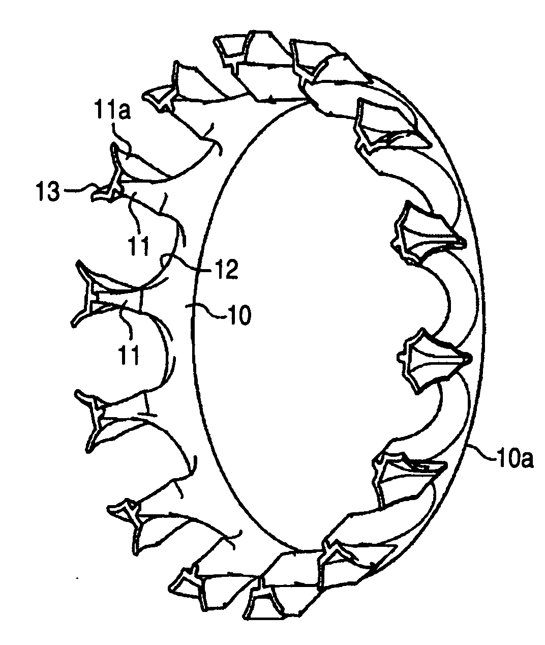
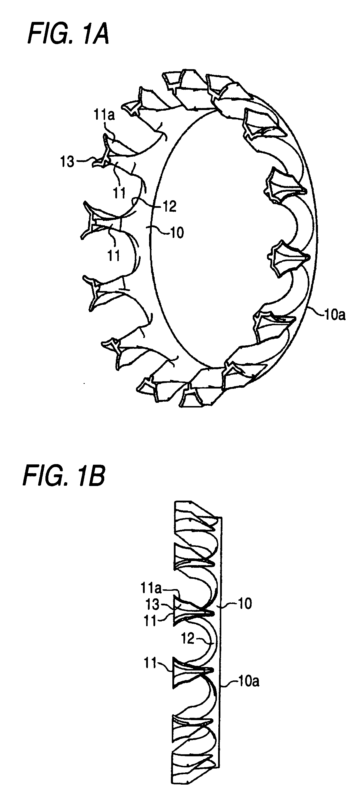
[0029]FIG. 1A is a perspective view illustrating the perspective structure of such a resin cage for the ball bearing according to an embodiment of the invention. FIG. 1B is a side view illustrating the side structure of the resin cage for the ball bearing according to the embodiment of the invention. As illustrated in FIGS. 1A and 1B, the resin cage is formed into a substantially crown-like shape, and includes an annular base portion 10, and a plurality of claw portions 11 (the number of the claw portions 11 is, e.g., 14 in an example illustrated in FIGS. 1A and 1B) which are formed to be arranged at constant intervals on the circumference of the base portion 10 and to protrude therefrom. A concave-s


PUM


Abstract

It is a cage that is formed of a resin and that holds balls serving as rolling elements. The cage includes an annular base portion, and a plurality of claw portions that are formed to be arranged at constant intervals on the circumference of the base portion and to protrude therefrom. A pocket for accommodating the ball is formed between each pair of adjacent ones of the claw portions. In the resin cage for a ball bearing, thinning recesses are formed in end parts 11a of the claw portions and a rear surface of the base portion, respectively.

Description


Claims


Application Information

Patent Timeline
Owner JTEKT CORP
Why Eureka
Try Eureka