Combination steamer
- Summary
- Abstract
- Description
- Claims
- Application Information
AI Technical Summary
Benefits of technology
Problems solved by technology
Method used
Image

Examples
first embodiment
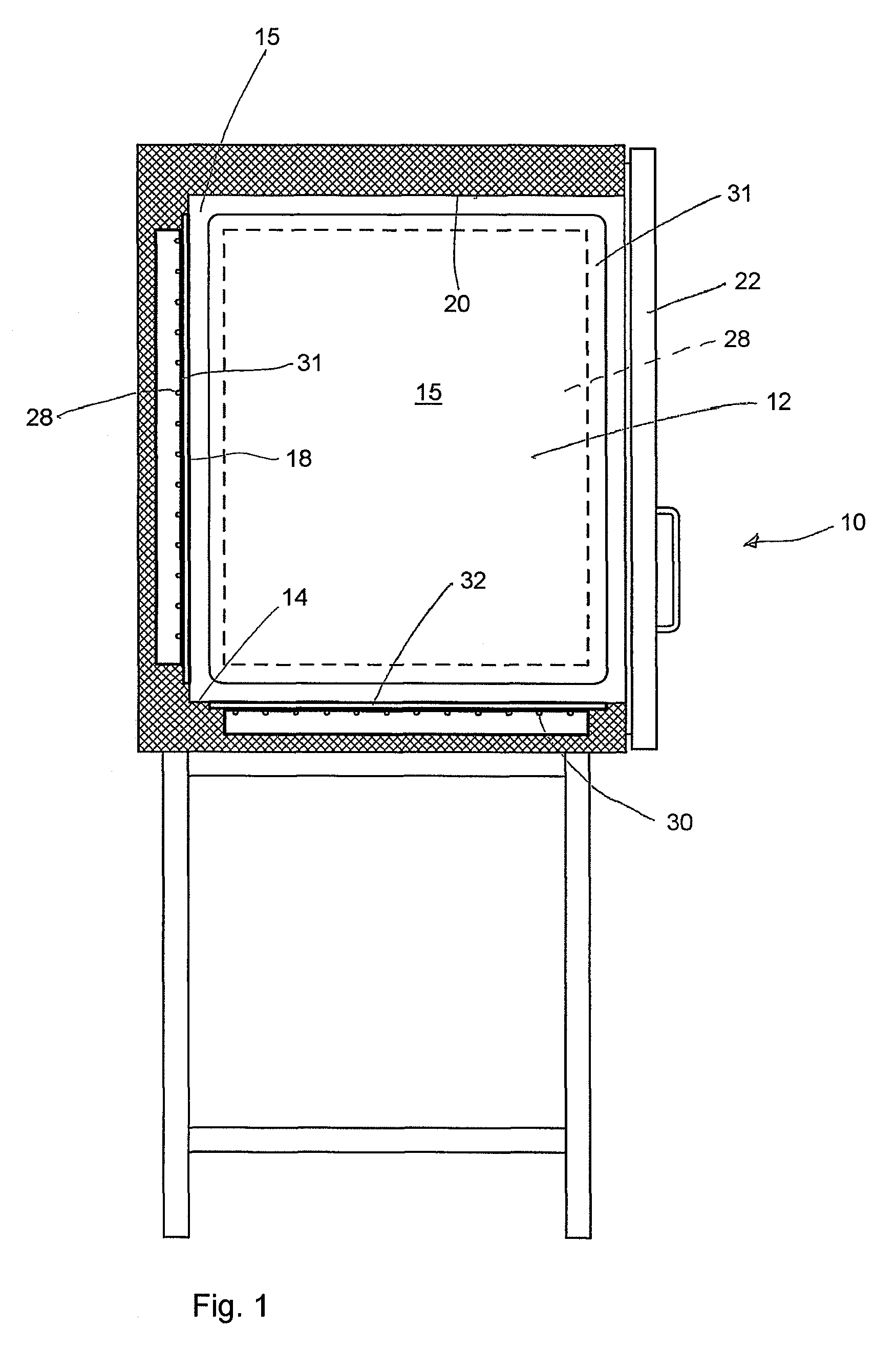
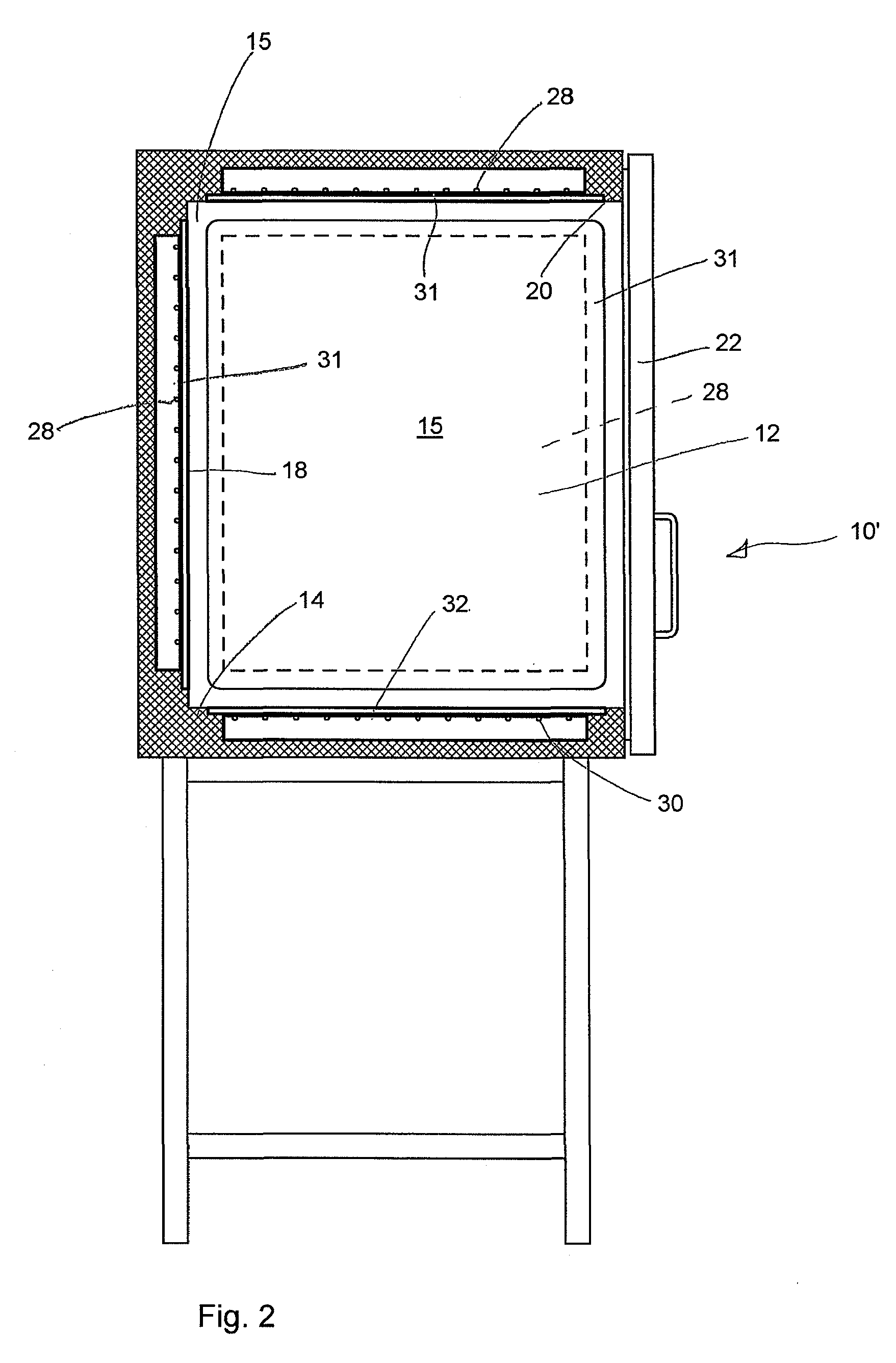
[0030]The two opposing side walls 15 and 16 and the rear wall 18 (as mentioned above, the side wall 16 is not visible in FIG. 1 and is shown in FIG. 4) in the combination steamer 10 have the same architecture as the floor 14 and are each formed as heating panels 31 provided with a first heater 28. A fourth side wall is not present but is instead formed by an opening offering access to the cooking chamber 12, which opening can be closed by means of the door 22. Unlike the prior art described above, the side walls 15, 16, and the rear wall 18 are also continuous walls, and the first heater is disposed behind these walls, that is to say, outside the cooking chamber 12. Each of the heating panels 31 is composed of a plate made of glass-ceramics or the like or of a metallic multilayered material and is embedded in the wall and performs the function of delimiting the cooking chamber laterally whilst making it possible to heat the cooking chamber without any need for the first heater to be di
third embodiment
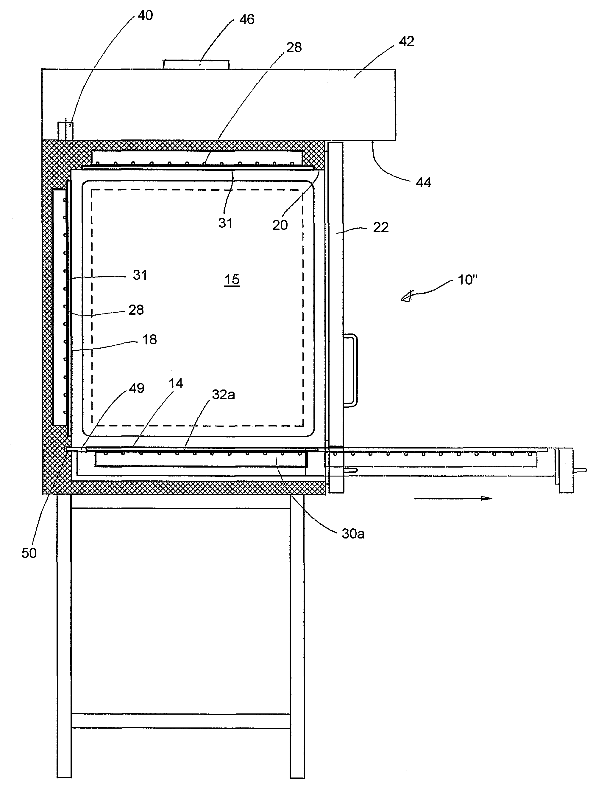
[0034]FIG. 3 shows a combination steamer designated as a whole by reference numeral 10″ as the invention. In the combination steamer 10″, the cook top 32 is designed as one that can be retracted from the cooking chamber 12 in the manner of a drawer, as shown in FIG. 3. FIG. 4 is a front view of the combination steamer 10″, with the door 22 of the cooking chamber 12 not shown for the sake of clarity. In combination steamer 10″ also, the cook top 32 forms the floor and thus forms the bottom delimitation of the cooking chamber 12. The ability of the cook top 32 to be retracted to a position shown in FIG. 3 makes it easier for the user of the combination steamer 10″ to work when the cook top 32 is used as a stove. As in the case of the first two embodiments, the cook top 32 can comprise a plurality of hot plates and the second heater 30 can comprise a plurality of heating means assigned individually to each of the hot plates. In the exemplary embodiment shown in FIGS. 3 and 4, the second h
PUM
 Abstract
Description
Claims
Application Information
 - R&D Engineer
- R&D Manager
- IP Professional
- Industry Leading Data Capabilities
- Powerful AI technology
- Patent DNA Extraction
Browse by: Latest US Patents, China's latest patents, Technical Efficacy Thesaurus, Application Domain, Technology Topic.
© 2024 PatSnap. All rights reserved.Legal|Privacy policy|Modern Slavery Act Transparency Statement|Sitemap