Method and apparatus for buried word line formation

Active Publication Date: 2012-02-16
MICRON TECH INC
View PDF10 Cites 16 Cited by
  • Summary
  • Abstract
  • Description
  • Claims
  • Application Information

AI Technical Summary

Problems solved by technology

Some problems arise during the subsequent etching of the word line trenches 110.
On the other hand, it is difficult to clean Tungsten from the bottom of the word line trench 110 and thus residues of Tungsten may ca

Method used


Image

  • Method and apparatus for buried word line formation
  • Method and apparatus for buried word line formation
  • Method and apparatus for buried word line formation

Examples


Embodiment Construction

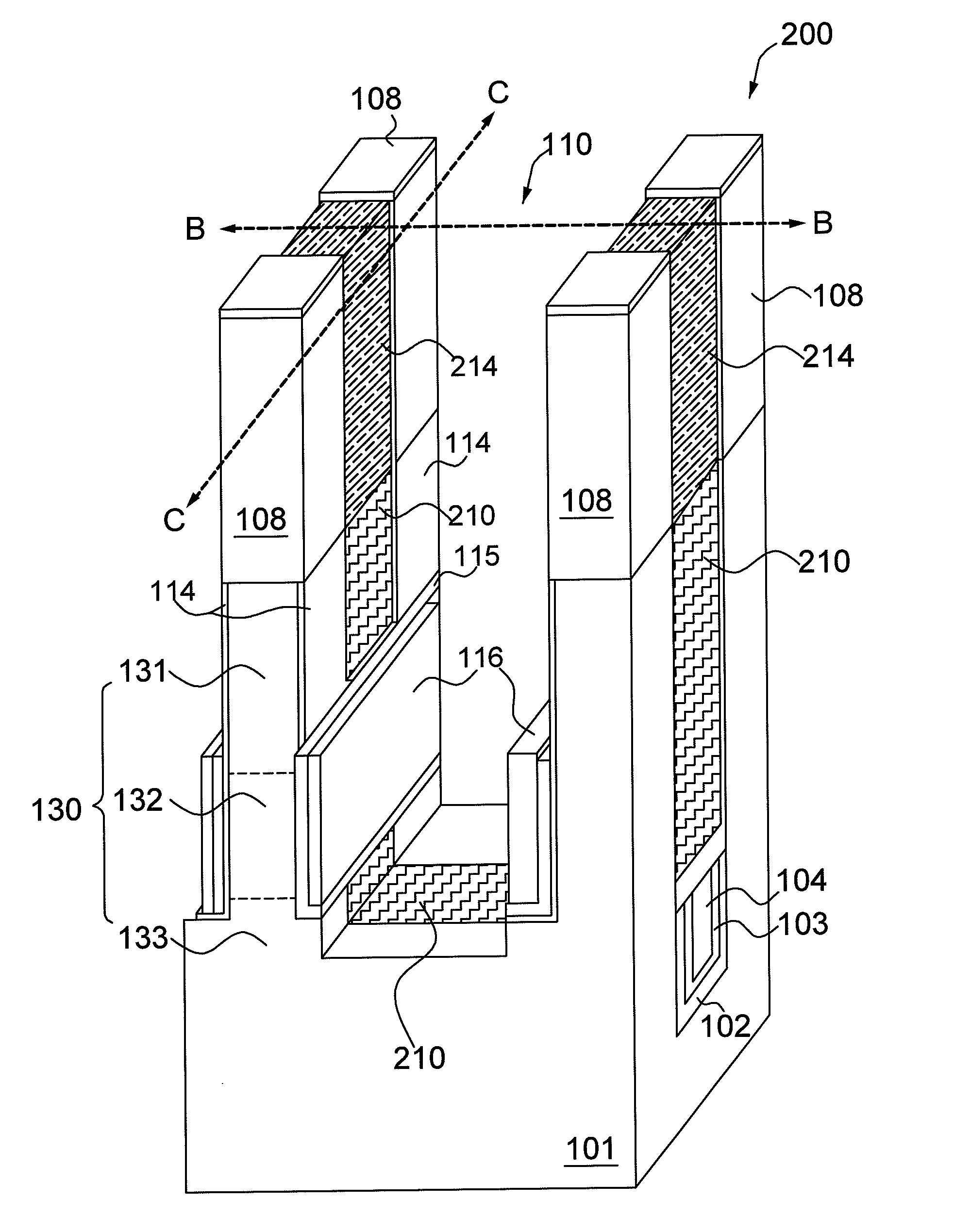
[0024]FIG. 2A is a perspective view of a memory cell having a generally smooth word line trench according to an embodiment of the invention. Referring to FIG. 2A, a memory cell 200 includes buried bit and word lines 104, 116 coupled to a vertical access transistor 130 disposed in a semiconductor substrate 101. The memory cell 200 can be any type of memory cell employing buried bit and word lines 104, 116, such as a DRAM cell, a MRAM cell, a FLASH cell, etc. For ease of description, the memory cell 200 is described herein as a DRAM cell. However, those skilled in the art will appreciate that the embodiments described herein are readily applicable to other types of memory cells having buried bit and word lines 104, 116.

[0025]In this specification, common reference numerals have been employed where common elements have the same function as in all drawings and embodiments described herein.

[0026]FIG. 2B is a cross-section view taken along the cut line B-B of FIG. 2A. Two adjacent word lines


PUM


Abstract

An integrated circuit with a memory cell is disclosed. The integrated circuit with a memory cell includes: a word line disposed in a word line trench of a substrate; a bit line disposed below the word line in a bit line trench and extending orthogonal to the word line; and, a separating layer disposed above the bit line in the bit line trench that separates the word line from the bit line; wherein an etching rate of the separating layer approaches that of the substrate.

Description


Claims


Application Information

Patent Timeline
Owner MICRON TECH INC
Why Eureka
Try Eureka