Liquid crystal display

Inactive Publication Date: 2012-04-19
CHUNGHWA PICTURE TUBES LTD
View PDF5 Cites 12 Cited by
  • Summary
  • Abstract
  • Description
  • Claims
  • Application Information

AI Technical Summary

Benefits of technology

[0009]Therefore, the main object of the present invention is to provide an LCD capable of improving its aperture ratio to solve problems occurring in the prior art. The present invention can not only overcome the limit of manufacturing precision but also increase brightness as well as reduce manufacturing costs.

Problems solved by technology

The larger the gap d1 is, the smaller the aperture ratio of a pixel and the smaller the transmission ratio become, further increasing the cost of the conventional TFT array panel 10.

Method used


Image

  • Liquid crystal display
  • Liquid crystal display
  • Liquid crystal display

Examples


Example

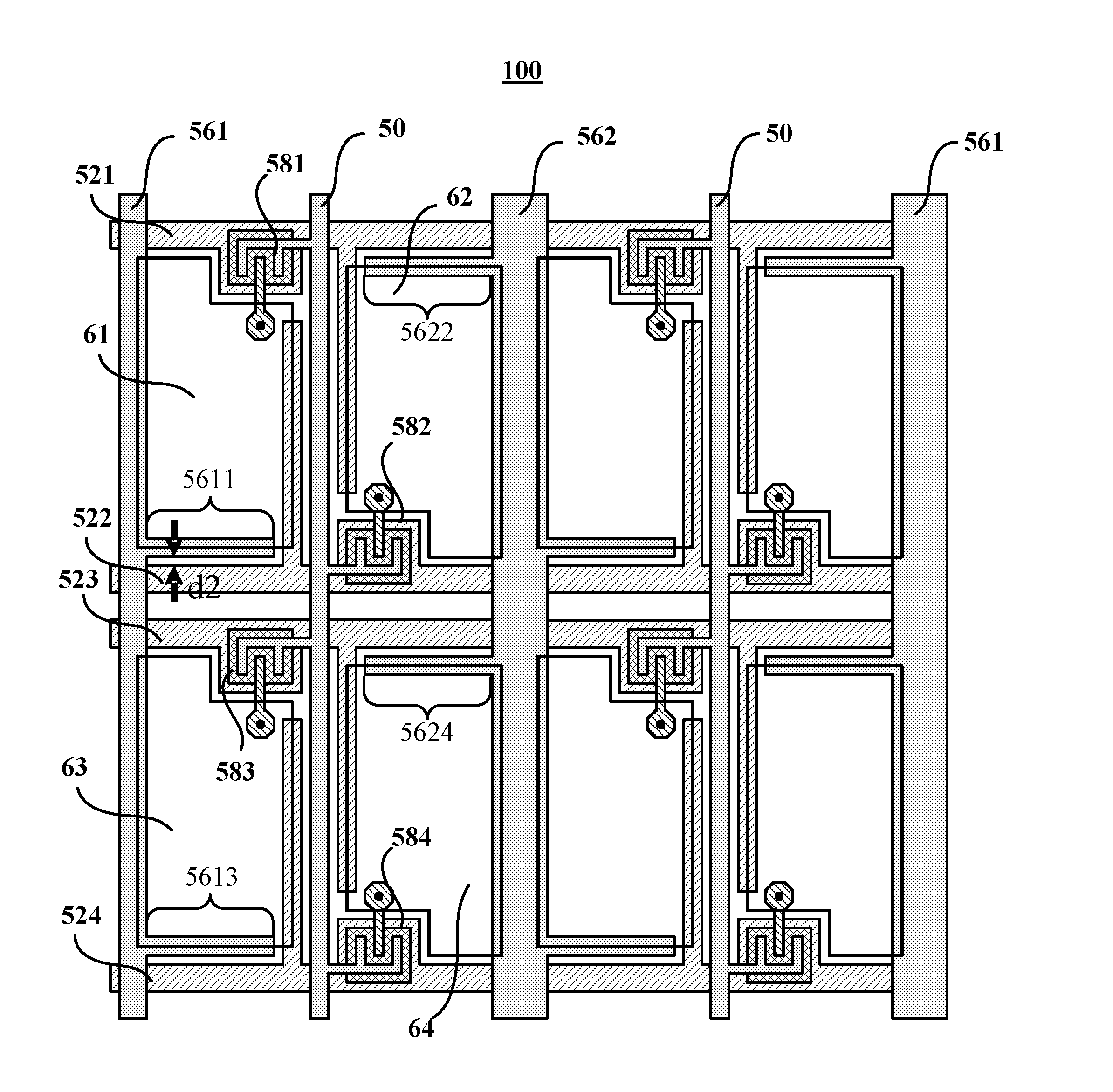
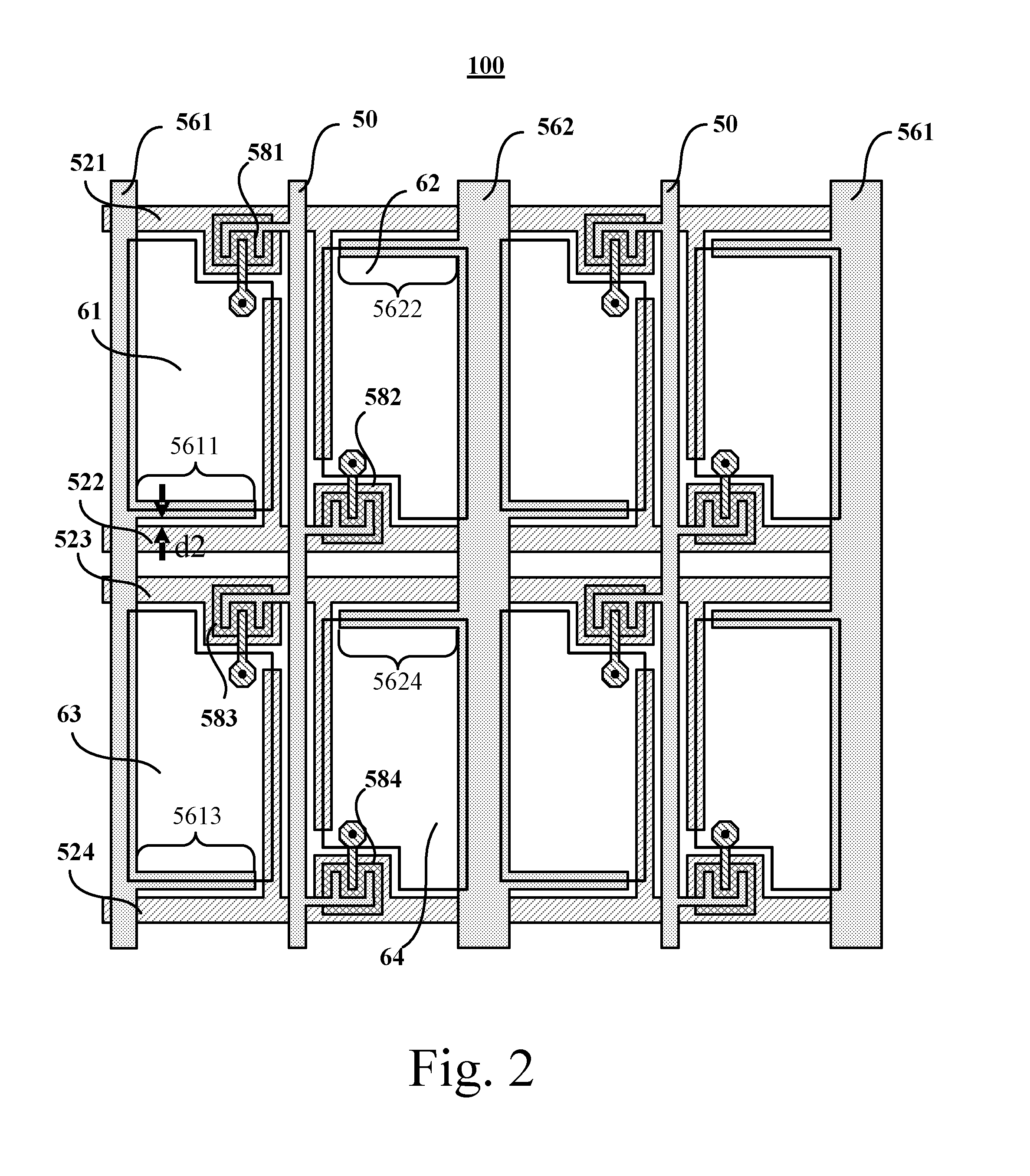
[0025]Refer to FIG. 2, which is a layout of a TFT array panel 100 according to a first embodiment of the present invention. The TFT array panel 100 used in an LCD comprises a first pixel electrode 61, a second pixel electrode 62, a third pixel electrode 63, a fourth pixel electrode 64, a first scan line 521, a second scan line 522, a third scan line 523, a fourth scan line 524, a data line 50, transistors 581-584, a first storage capacitor electrode line 561, and a second storage capacitor electrode line 562.

[0026]The first pixel electrode 61 is electrically connected to the first scan line 521 and the data line 50 via the transistor 581. The second pixel electrode 62 is electrically connected to the second scan line 522 and the data line 50 via the transistor 582. The third pixel electrode 63 is electrically connected to the third scan line 523 and the data line 50 via the transistor 583. The fourth pixel electrode 64 is electrically connected to the fourth scan line 524 and the data


PUM


Abstract

An LCD includes a first pixel electrode coupled to a first scan line and a data line, and a second pixel electrode coupled to a second scan line and the data line. A first and a second storage capacitor electrode lines are at two sides of the data line and across the scan lines. A first storage capacitor electrode extension line is extended out of the first storage capacitor electrode line and toward the data line, and a second storage capacitor electrode extension line is extended out of the second storage capacitor electrode line and toward the data line. The first pixel electrode and second pixel electrode partly overlap the first and the second storage capacitor electrode extension lines, respectively. Since the storage capacitor electrode line and the scan line is formed on different metal layer, a gap between the storage capacitor electrode line and the scan line is shortened.

Description


Claims


Application Information

Patent Timeline
Owner CHUNGHWA PICTURE TUBES LTD
Why Eureka
Try Eureka