Urea solution apparatus for vehicles

a technology for urea solution and vehicle body, which is applied in the direction of tank vehicles, machines/engines, transportation items, etc., can solve the problems of urea solution storage tanks occupying limited internal space of car body, serious air pollution, and problems related to urea scr systems, etc., and achieves convenient use and expansion of usable parts.

Inactive Publication Date: 2015-04-30
HYUNDAI MOTOR CO LTD
View PDF2 Cites 11 Cited by
  • Summary
  • Abstract
  • Description
  • Claims
  • Application Information

AI Technical Summary

Benefits of technology

The technical effect described by this patented device is that it provides a way to store high-capacity urease solutions inside cars without taking up too much room on them's back or reducing their functionality. This makes charging these liquids easier while also improving its overall appearance compared with traditional methods like adding extra parts at different locations within the car itself.

Problems solved by technology

The technical problem addressed in this patented text relates to improving efficiency within vehicles' engines while minimizing emissions caused by excess NOX levels during operation. This can include controlling the comburent temperatures inside the engine to lower harmful gases produced without increasing their production costs. Additionally, maintaining efficient evacuation systems helps prevent condensate deposits on certain parts of the vehicle cabin where the urease-catalysed reduction process occurs.

Method used


Image

  • Urea solution apparatus for vehicles
  • Urea solution apparatus for vehicles
  • Urea solution apparatus for vehicles

Examples


Embodiment Construction

[0042]Reference will now be made in detail to various embodiments of the present invention(s), examples of which are illustrated in the accompanying drawings and described below. While the invention(s) will be described in conjunction with exemplary embodiments, it will be understood that the present description is not intended to limit the invention(s) to those exemplary embodiments. On the contrary, the invention(s) is / are intended to cover not only the exemplary embodiments, but also various alternatives, modifications, equivalents and other embodiments, which may be included within the spirit and scope of the invention as defined by the appended claims.

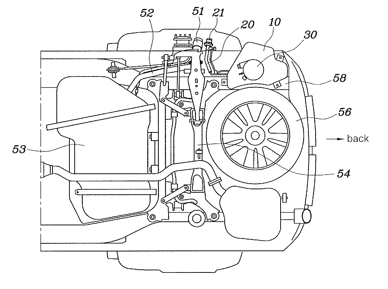
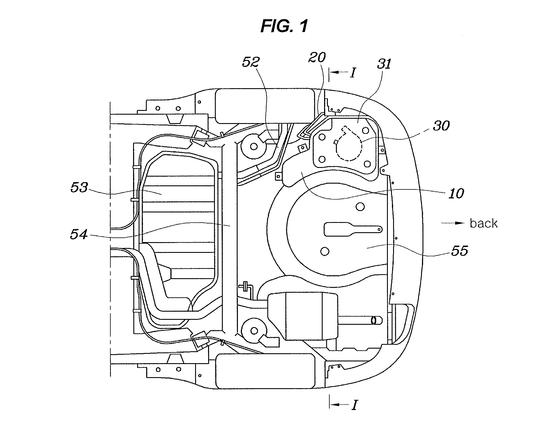
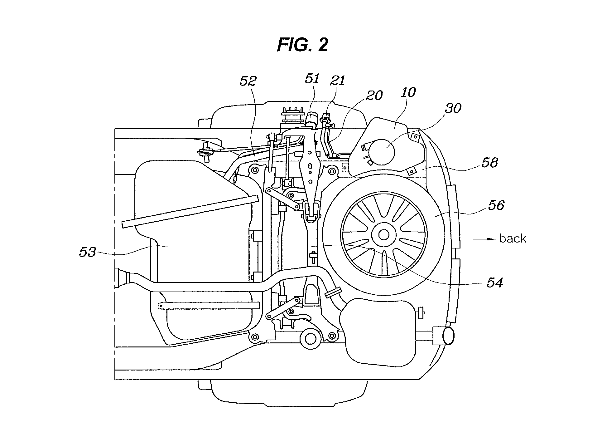
[0043]Hereinbelow, a urea solution apparatus for vehicles according to an exemplary embodiment of the present invention will be described in detail with reference to the accompanying drawings.

[0044]The present invention relates to a urea solution apparatus which is installed in a vehicle having a diesel engine and functions to puri


PUM


Abstract

A urea solution apparatus for a vehicle may include a urea solution storage tank installed in a side of a lower part in a rear part of a car body, and a urea solution pipe configured to inject a urea solution into the urea solution storage tank, wherein the urea solution pipe is connected to the urea solution storage tank in such a way that a urea solution injection nozzle of the urea solution pipe is located in a space in which a fuel inlet hole is provided.

Description


Claims


Application Information

Patent Timeline
Owner HYUNDAI MOTOR CO LTD
Why Eureka
Try Eureka